Electronics
Step 1
Last part of the guide describes the installation of the necessary electronics for operating the GoodEnoughCNC. There are many ways on how to wire our CNC.
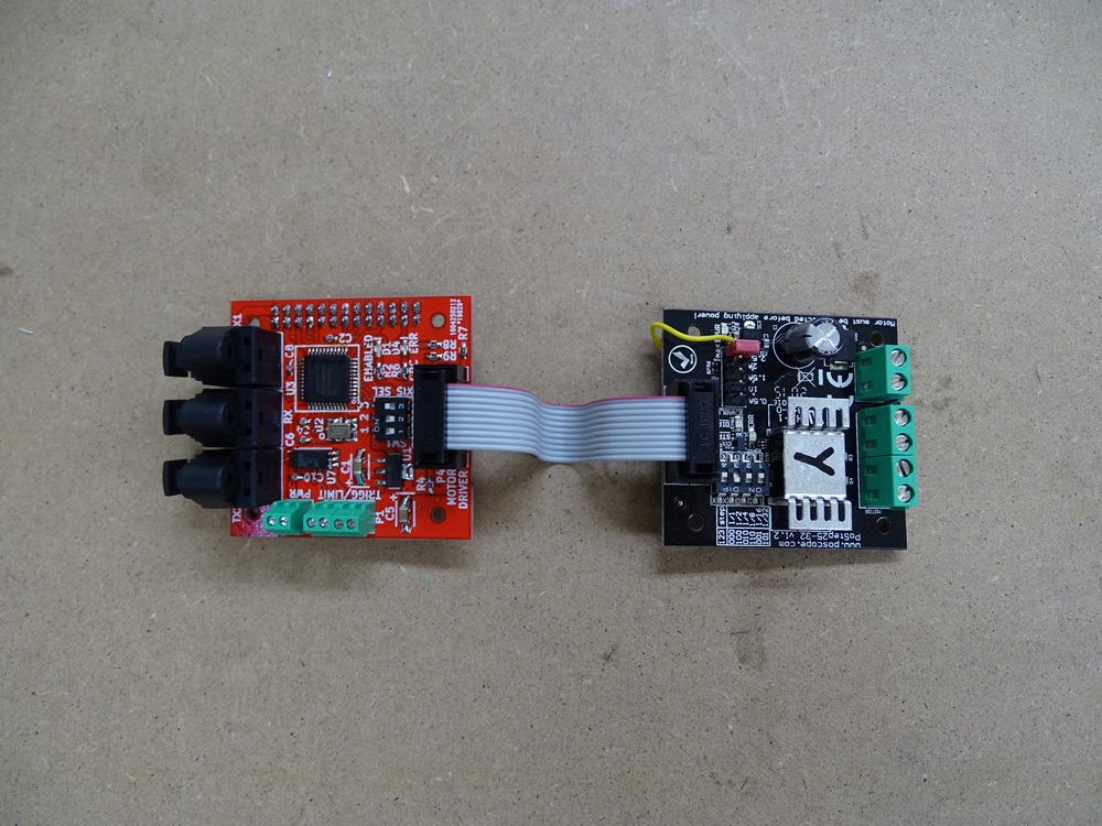
We used our own Toslink CNC system.
Step 2
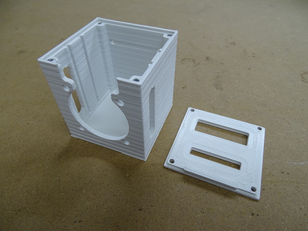
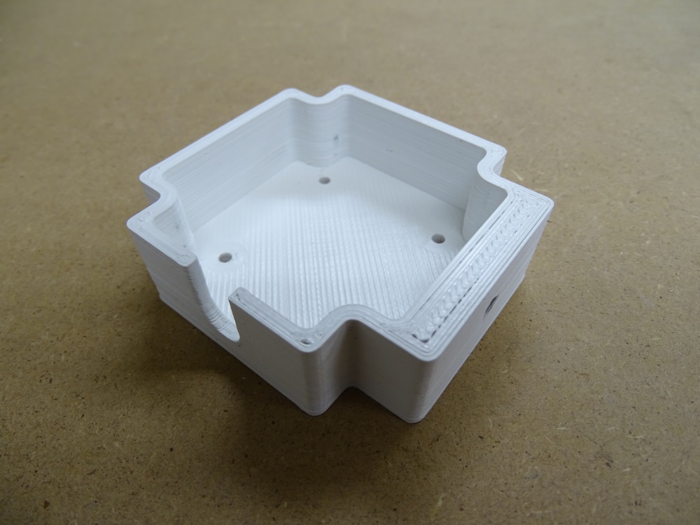
There is one Toslink board and one motor driver for each motor. For housing electronics for each motor we used 3D printed boxes. For fastening the boxes on motors there are three additional printed Fasteners.
Step 3
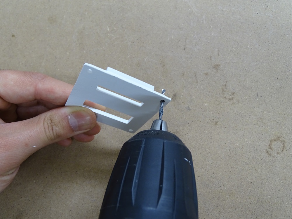
Redrill 3 mm holes on the covers. Repeat this step four times.
Parts needed:
- 4 x Electronics box cover
Step 4
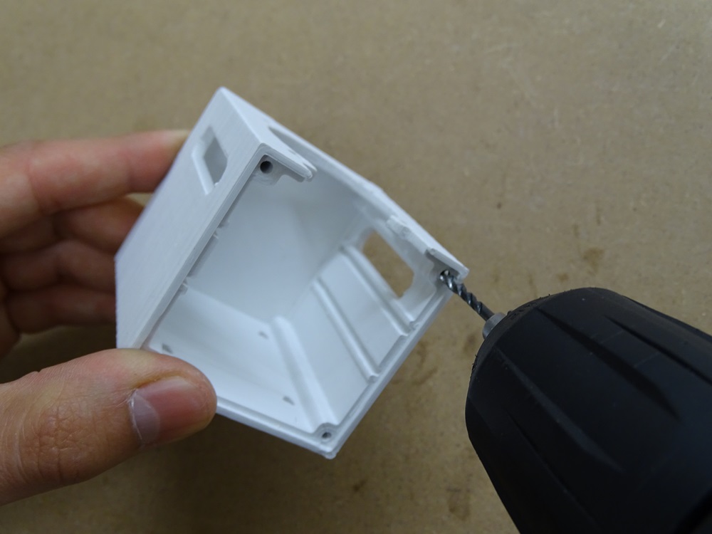
Redrill holes on the box with 2.5 mm drill or make M3 threaded holes. The depth of the holes should be around 15 mm.
Repeat this step four times.
Parts needed:
- 4 x Electronics box
Step 5
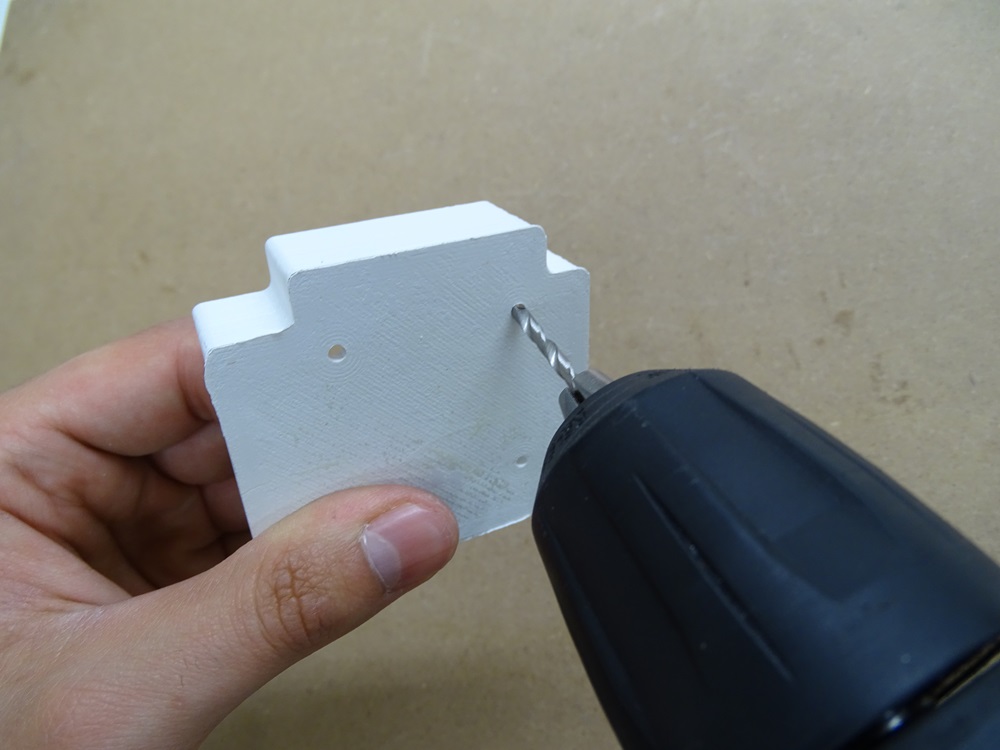
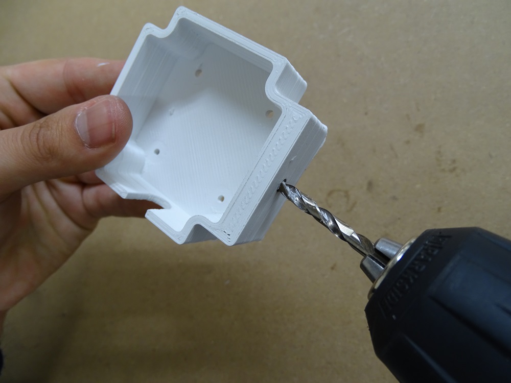
Redrill four smaller holes with 3 mm drill. For bigger hole use 4.5 mm drill or make M5 threaded hole.
Repeat this step three times.
Parts needed:
- 3 x Electronics box fastener
Step 6
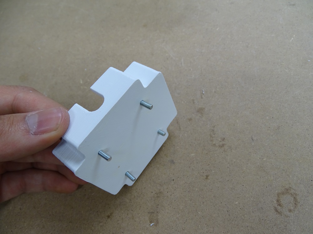
Put four M3x12 torx bolts into the Fastener.
Parts needed:
- 12 x ISO 14583 M3 x 12 torx bolt
Step 7
Screw together the fastener and the electornics box with four M3 hex nuts.
Repeat this step three times.
Parts needed:
- 12 x DIN 934 M3 hex nut
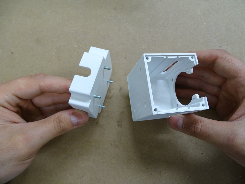
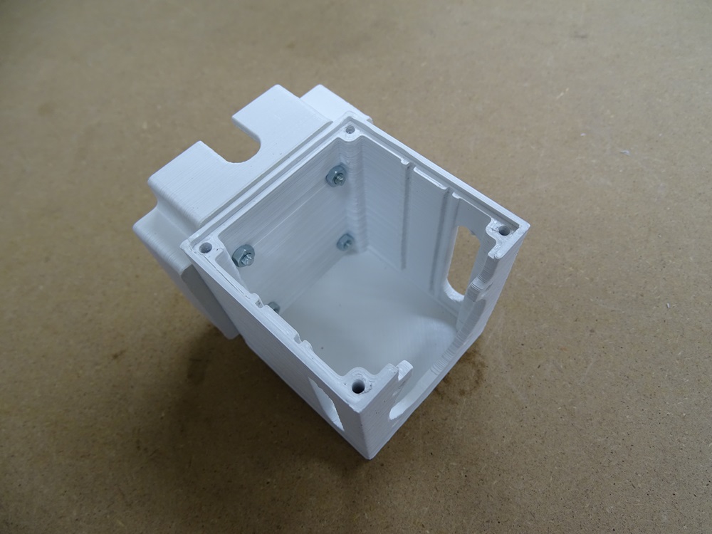
Step 8
Slide the connected motor driver and toslink board into the designated grooves on the Electronics box.
Repeat this step four times.
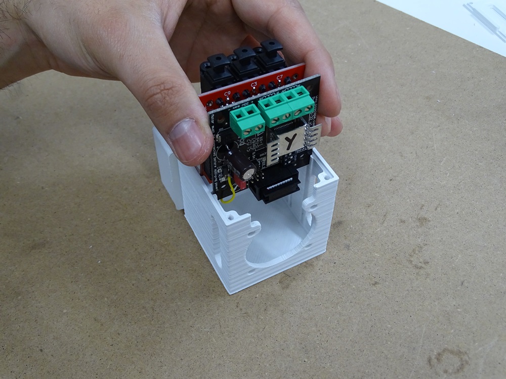
Step 9
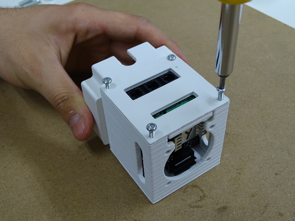
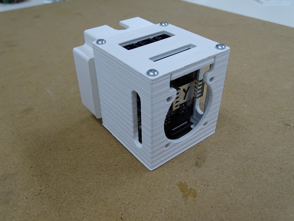
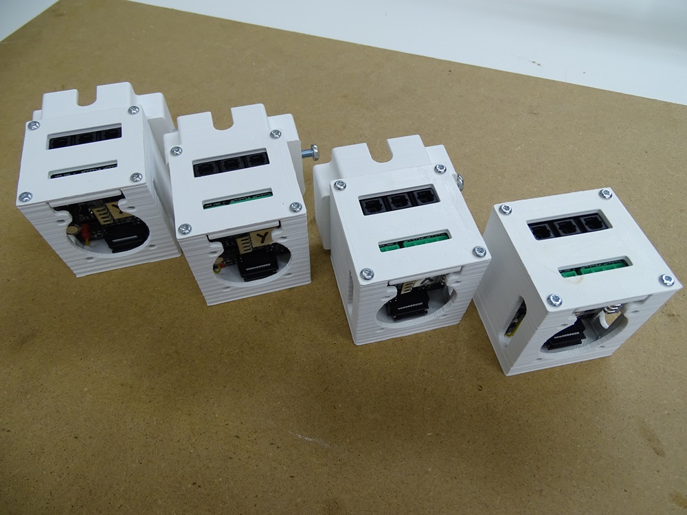
Fasten the Cover of the box with four M3 x 12 torx bolts. Repeat this step four times.
Make sure to label in which boxes are boards for Y1, Y2, X and Z axis.
Parts needed:
- 16 x ISO 14583 M3 x 12 torx bolt
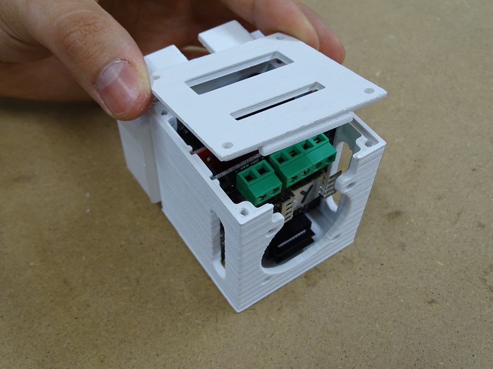
Step 10
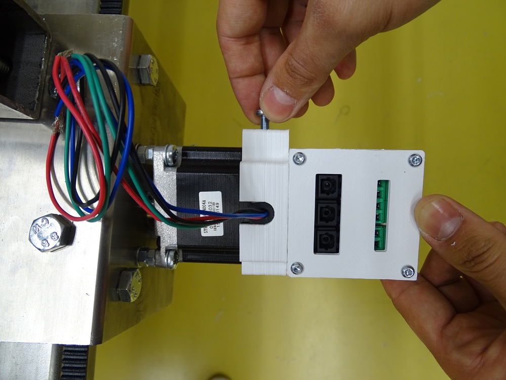
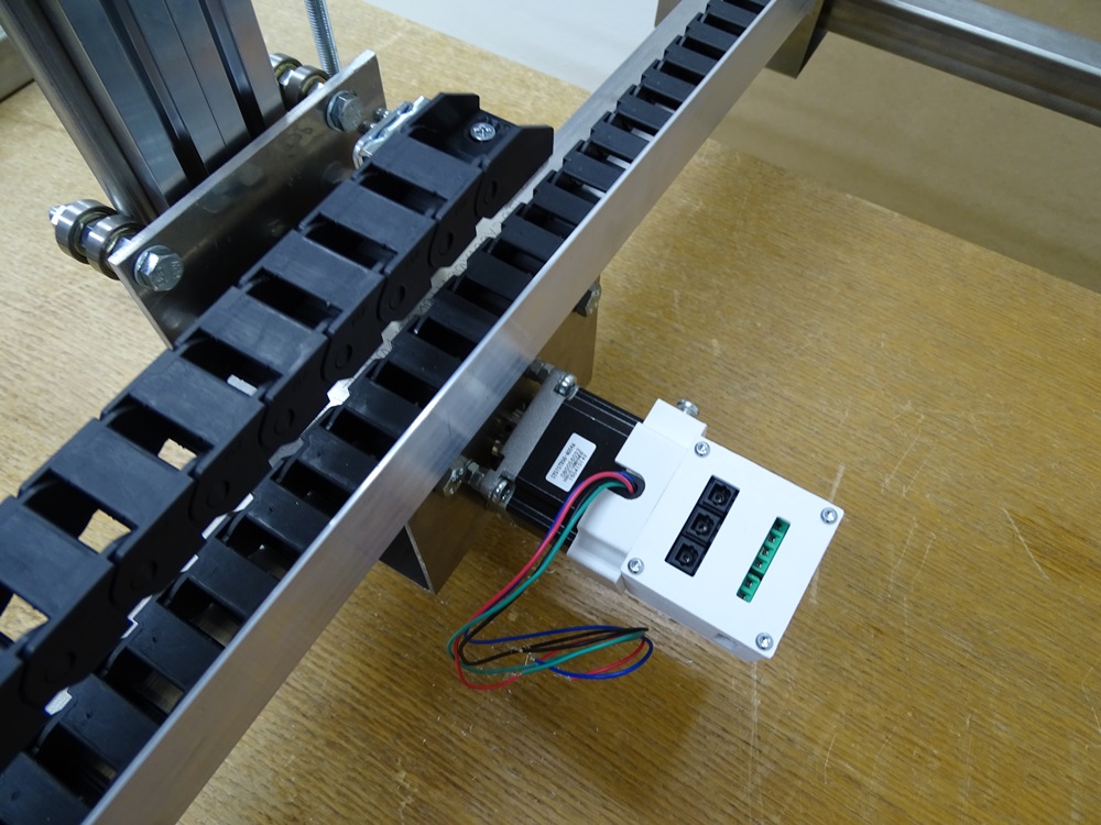
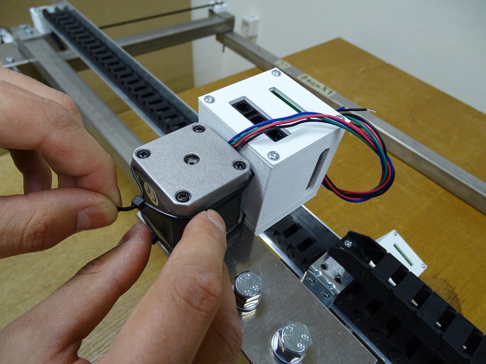
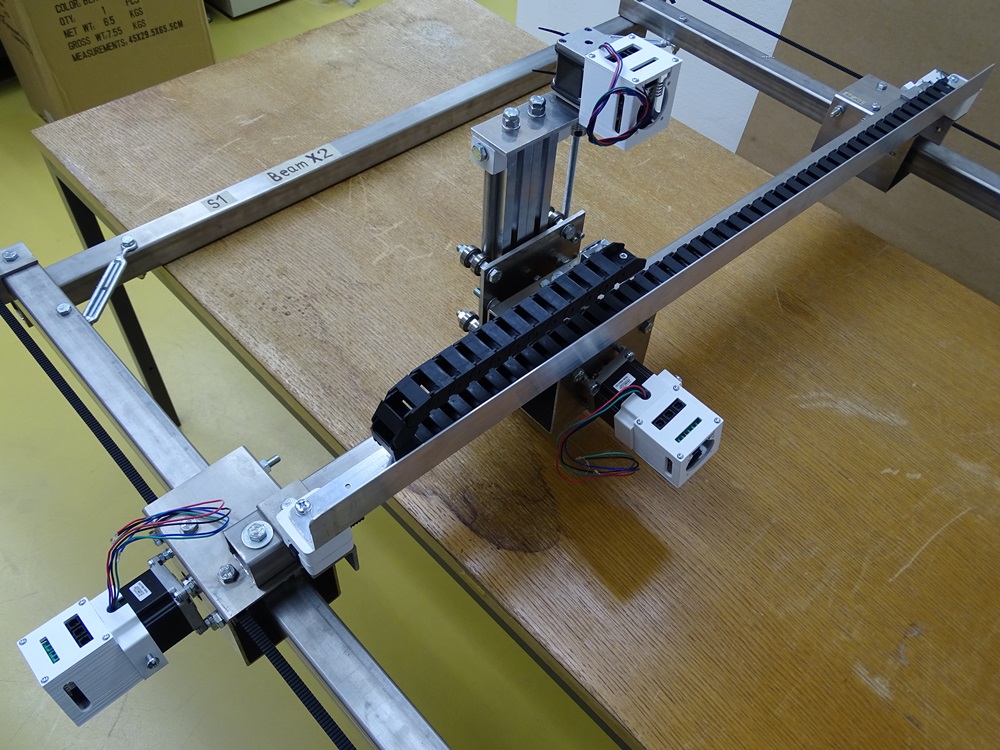
Fasten the boxes on the motors with any M5 bolt. Make sure that the right boxes are on the right Trolleys. Fasten the Electornics box for Z axis with two simple cable ties that run through the holes on the back of the box.
Parts needed:
- 3 x DIN 7985 M5 x 25
Step 11
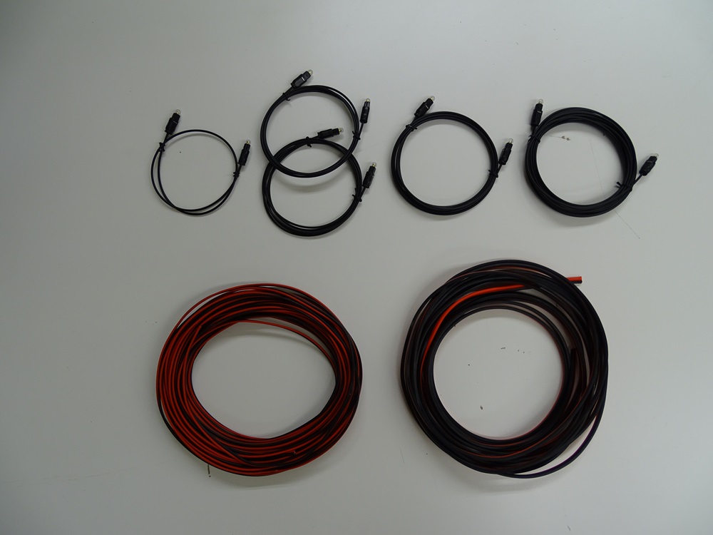
For wiring of the CNC we need 1.5 mm2 and 0.75 mm2 cables for power supply and optical cables for Toslink. Cable for power supply is cut to required length concurrently. Required lengths of the optical cables are 0.5 m, 1.5 m, 2 m, 2.5 m and 5 m, one of each.
Step 12
At every end of the power supply cable use wire ferrules.
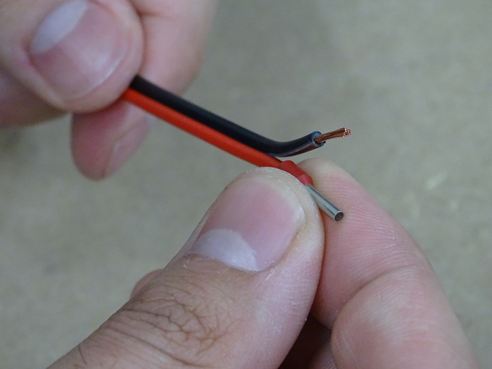
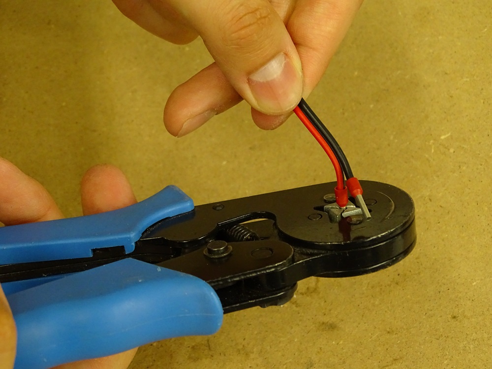
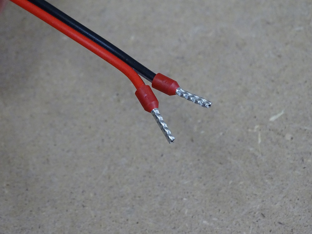
Step 13
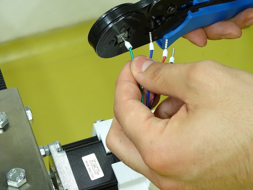
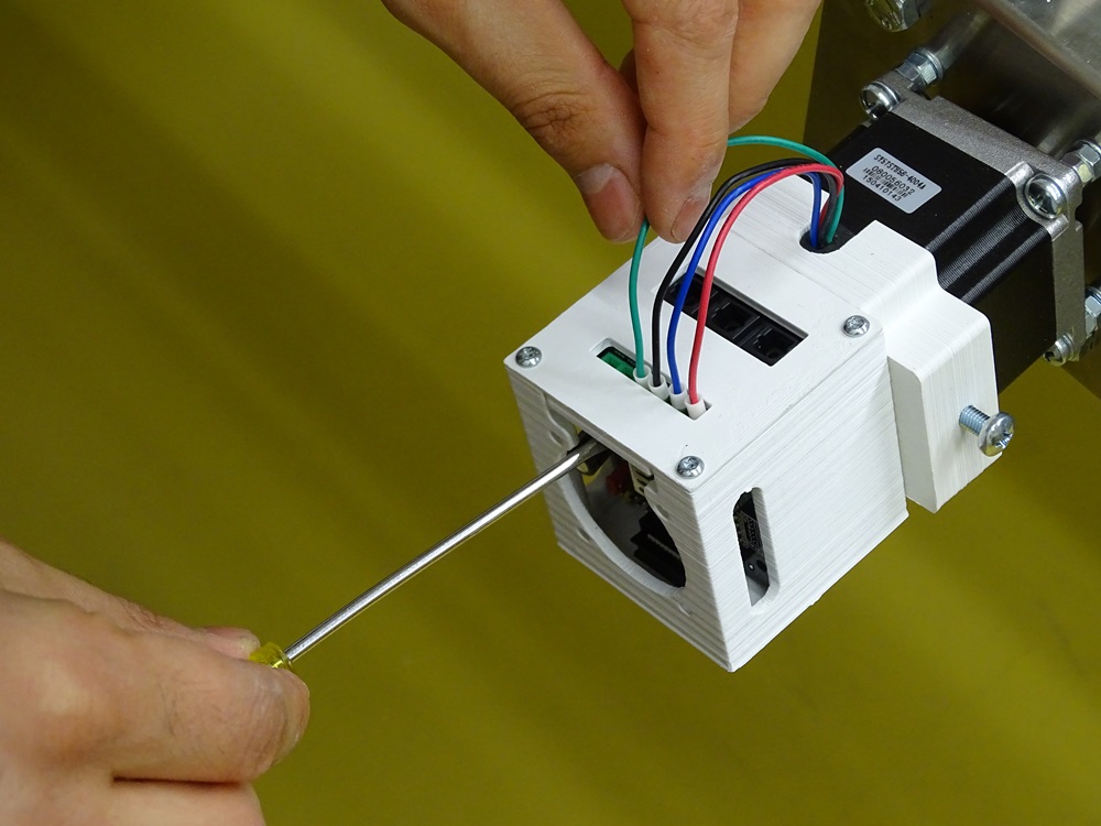
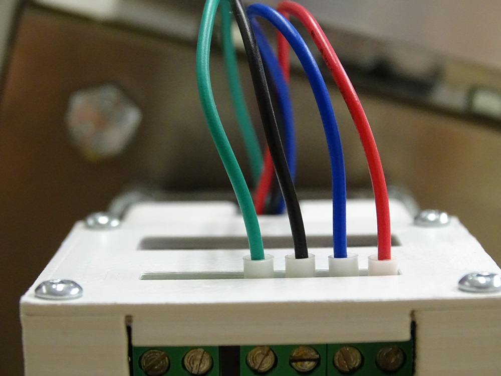
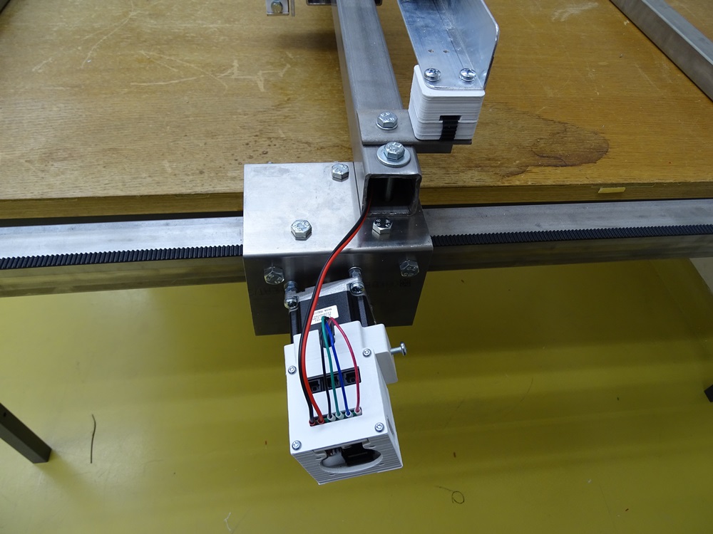
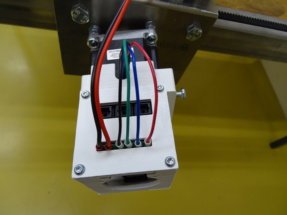
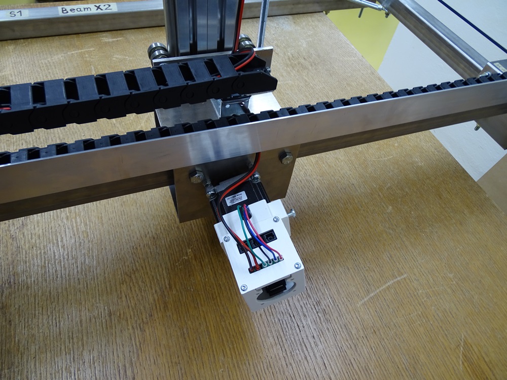
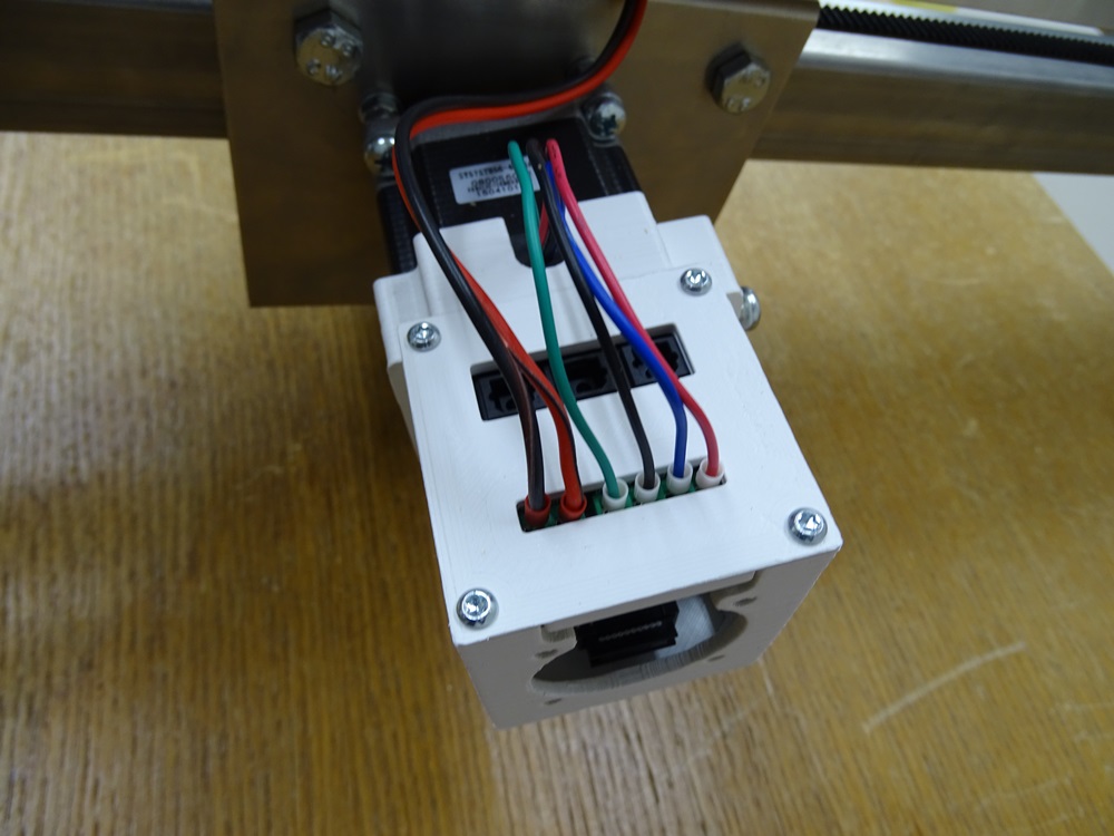
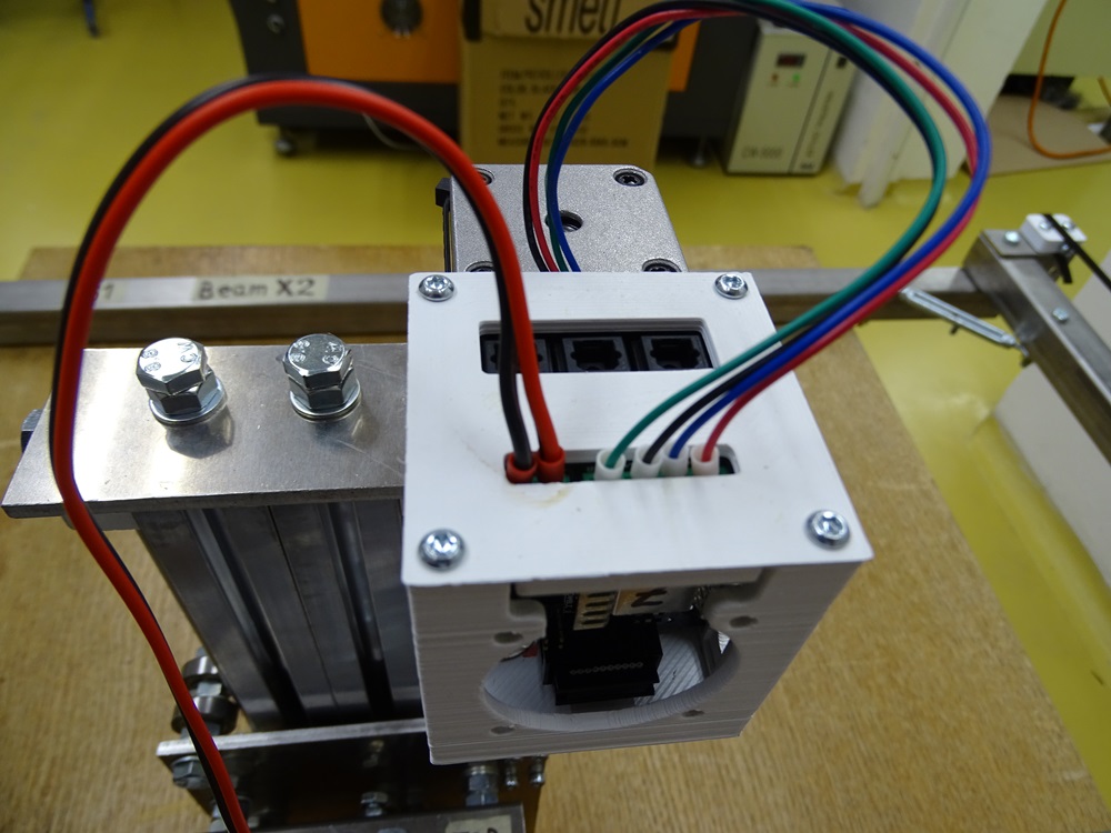
Start wiring the motors to the driver boards. Use wire ferrules. The correct order from left to right is green, black, blue and red.
Do this for all motors with the exception of Y2, where green and black wire must be switched.
Step 14
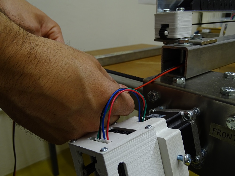
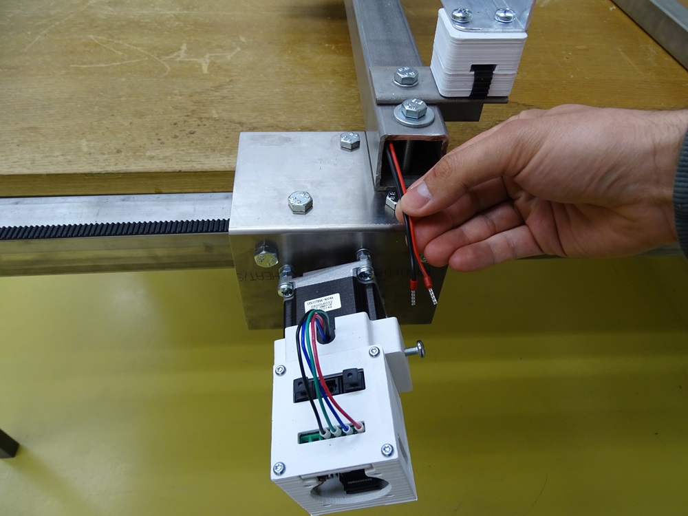
Put thin 0.75 mm2 wire from Y1 through the Beam X – Main to Y2. Connect the end of the wire to Y2.
Parts needed:
- 1 x 1.4 m 0.75 mm2 cable
Step 15
Put another 0.75 mm2 wire from Y1 through cable chain. Leave approximately 15 cm of extra cable.
Parts needed:
- 1 x 1.5 m 0.75 mm2 cable
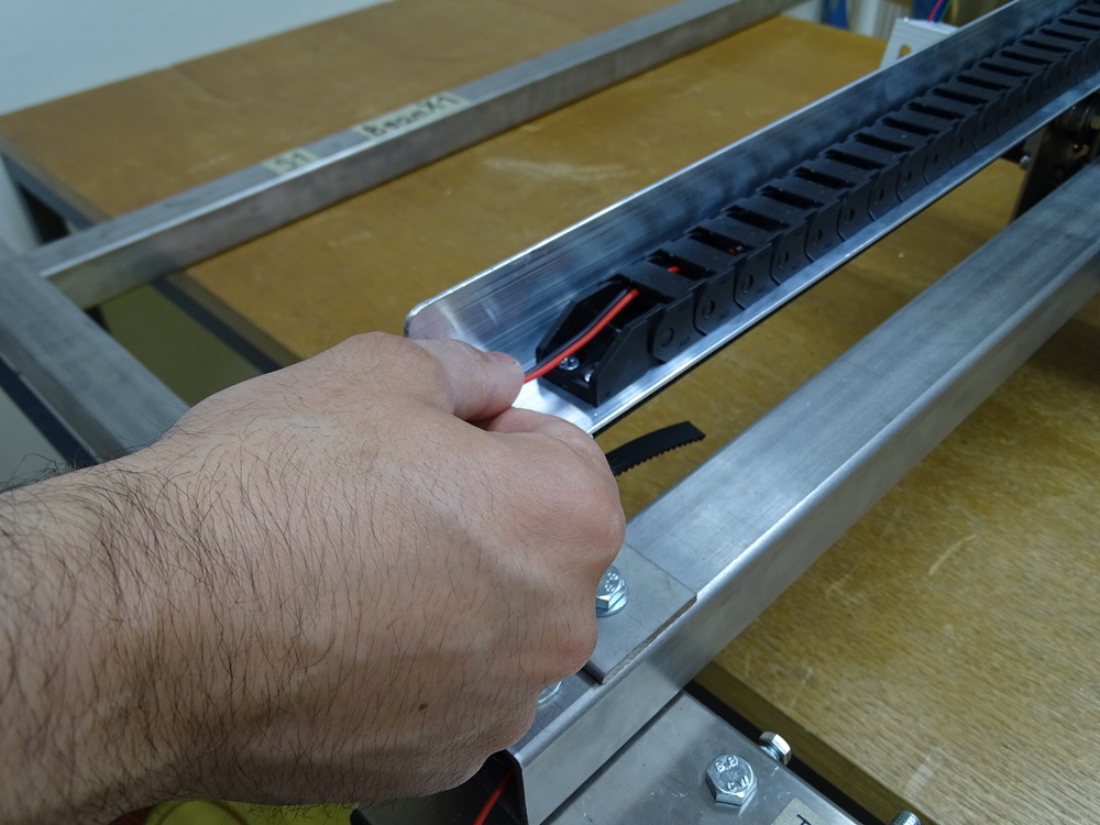
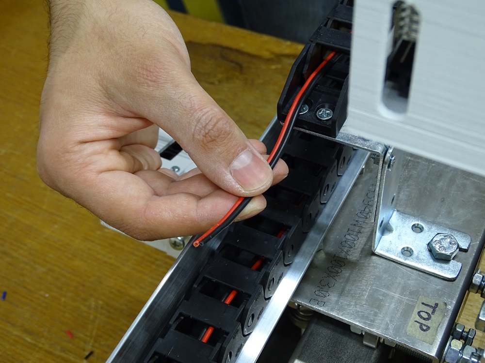
Step 16
Connect the two wires at Y1 together on the same side of the wire connector.
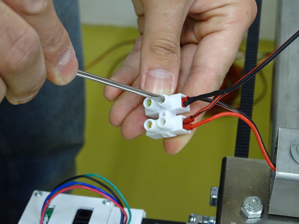
Step 17
On the other side of wire connector link together one thin 0.75 mm2 cable and one thick 1.5 mm2 cable. The thin cable goes to Y1 motor driver. The thick cable goes to the main power supply.
Parts needed:
- 1 x 2.5 m 1.5 mm2 cable
- 1 x 0.2 m 0.75 mm2 cable
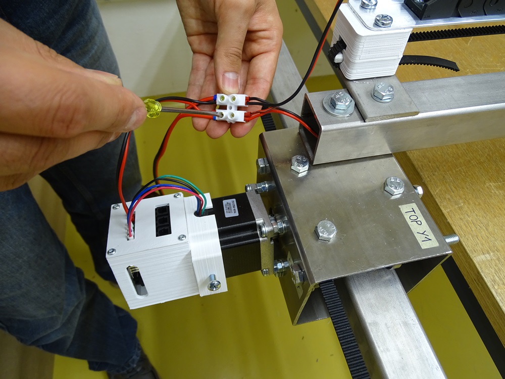
Step 18
To the cable at the end of the cable chain add two additional cables with cable connector. One runs to the X motor driver and one runs to Z motor driver.
Make sure that the cable to the Z motor is long enough.
Parts needed:
- 2 x 0.3m 0.75mm2 cable
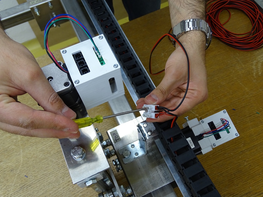
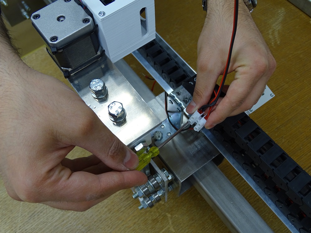
Step 19
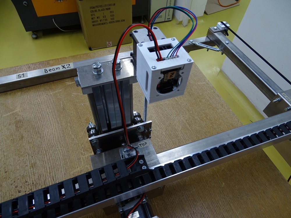
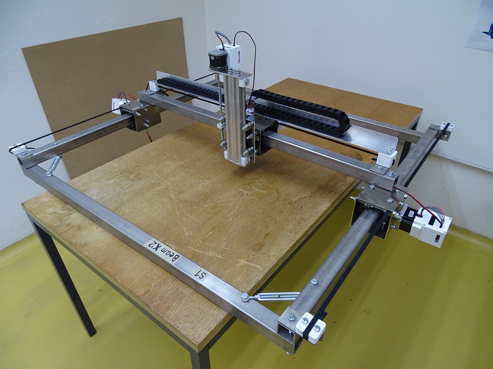
On the pictures it is shown the correct order of the cables on the motor driver for Y1.
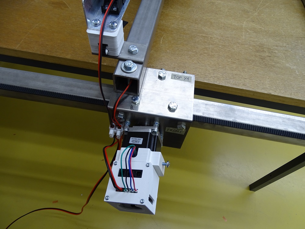
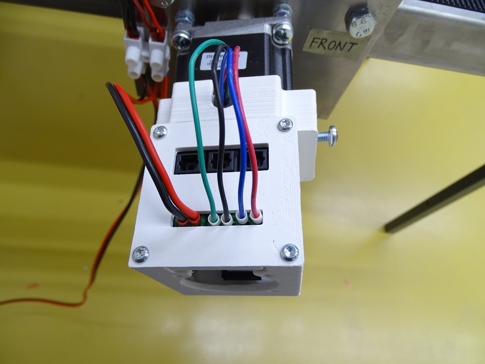
Step 20
On the pictures it is shown the correct order of the cables on the motor drivers for Y2.
Step 21
On the pictures it is shown the correct order of the cables on the motor drivers for X.
Step 22
On the pictures it is shown the correct order of the cables on the motor drivers for Z.
Step 23
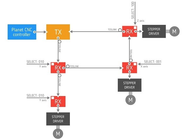
In the end, wire all Toslinks receivers with optical cables. Toslink receivers have one input receptacle in the middle and two output receptacles on the sides.
You can find more details about Toslink for CNC on Github.
Step 24
Start at the Y1. 2.5 m long optical cable from the transmitter goes in the middle receptacle on the Toslink board as input. From both left and right output receptacles go two cables.
Parts needed:
- 1 x 2.5 m optical cable
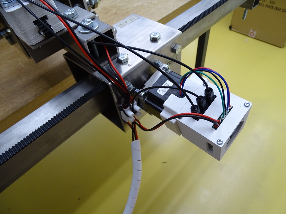
Step 25
First output optical cable from Y1 receiver is 1.5 m long and goes to the Y2 receiver through the Beam X – Main.
Parts needed:
- 1 x 1.5 m optical cable
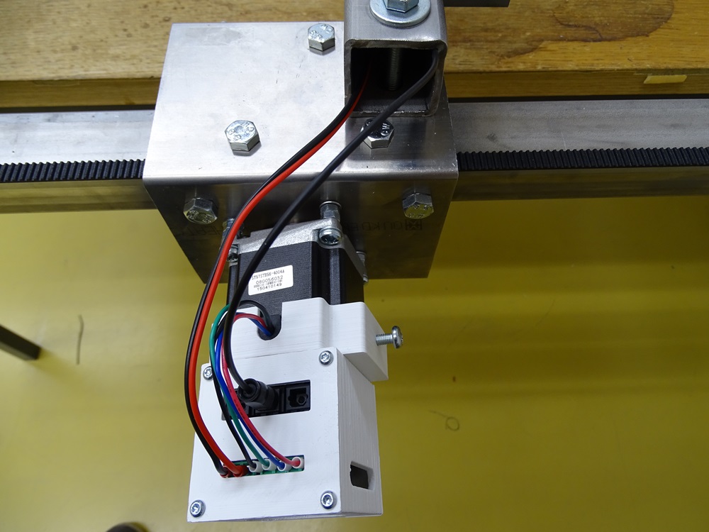
Step 26
Second output optical cable from the Y1 receiver is 2 m long and goes to the X receiver through the cable chain.
Parts needed:
- 1 x 2 m optical cable
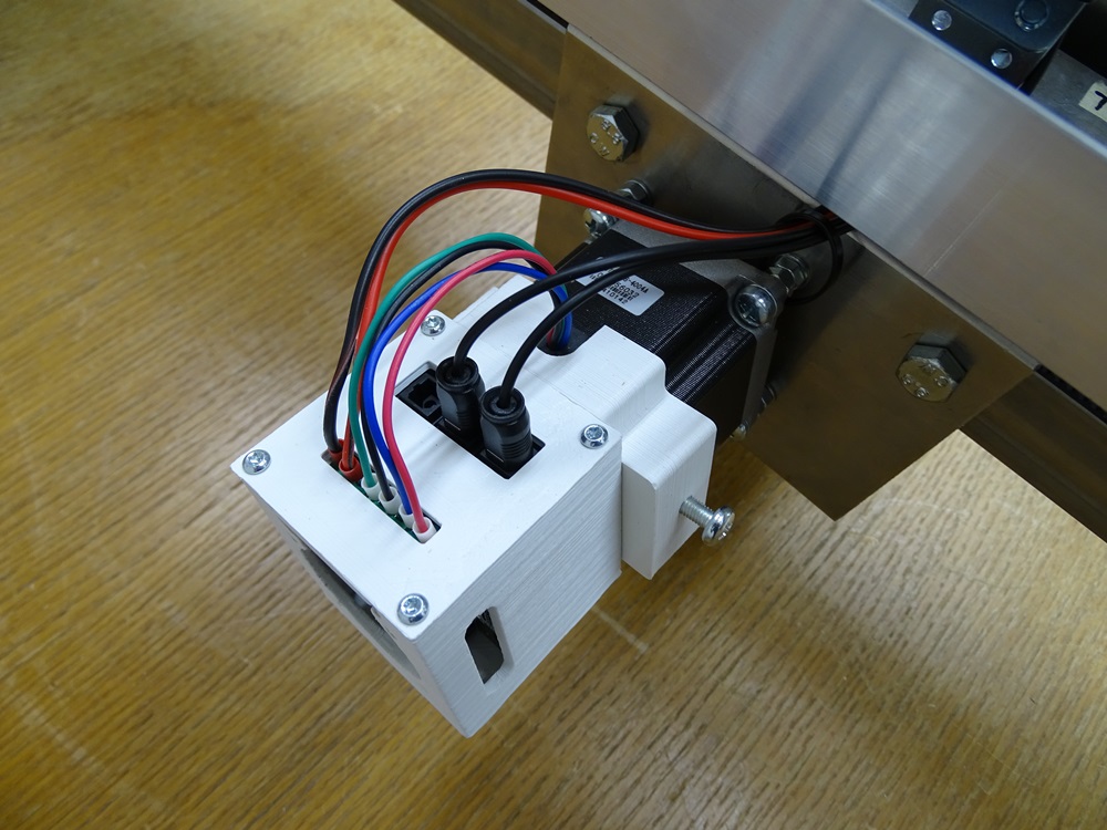
Step 27
From the X receiver goes 0.5 m long optical cable to the Z receiver. From the Z receiver goes 5 m long optical cable back to the Transmitter through the cable chain as a return link.
Parts needed:
- 1 x 0.5 m optical cable
- 1 x 5 m optical cable
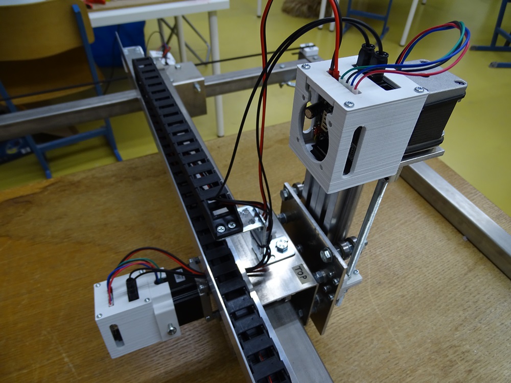
Updated less than a minute ago
