Frame - parts preparation
Step 1
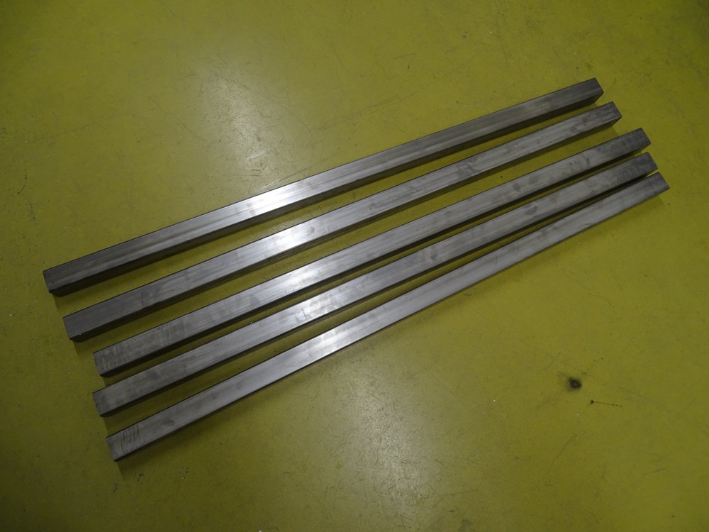
Cut 5 square profiles (40 mm x 40 mm with 3 mm thickness) of the length 1100 mm. Be sure that you achieve the rectangular cut.
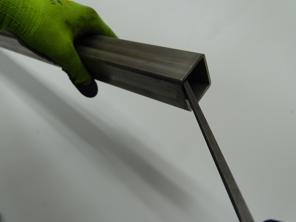
Smooth the rough edges with the file.
Mark the surfaces of the profile - start with S1 and rotate the profile clockwise marking sides S2, S3 and S4.
Parts:
5 x 40 x 40 x 1100 mm square profiles
Step 2
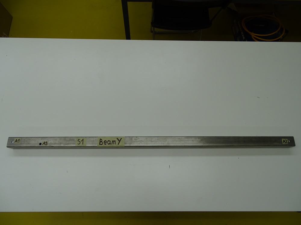
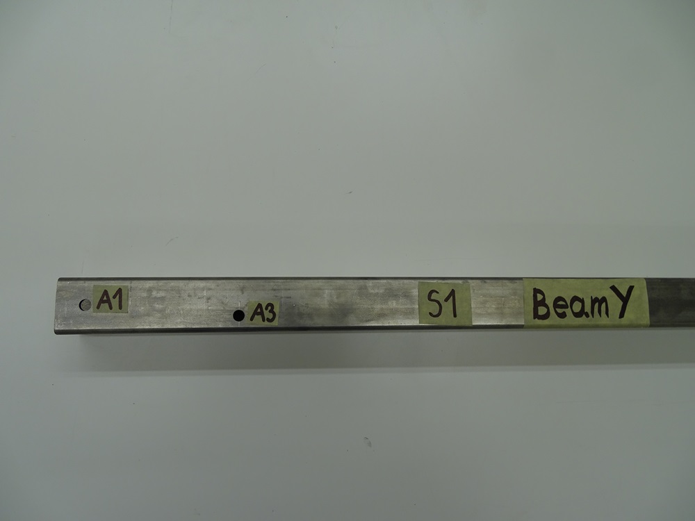
For the Beam Y drill three 8mm holes through both sides of the profile on surface S1 and S3. Holes A1 and A2 are in the center of the profile transversely and 20 mm longitudinally from the end edges. Hole A3 is longitudinally 125 mm and transversely 28 mm from profile edges. Make two identical Beams Y.
Step 3
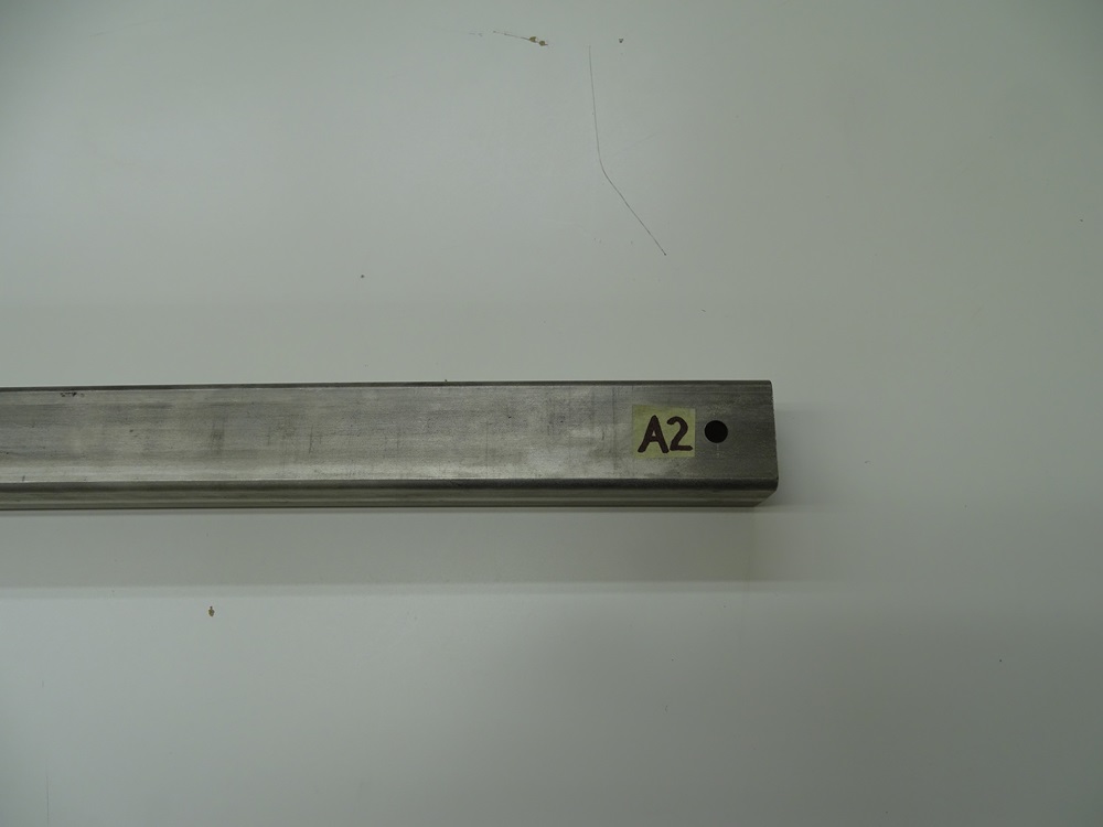
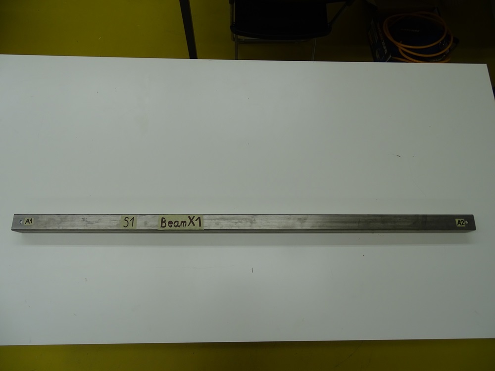
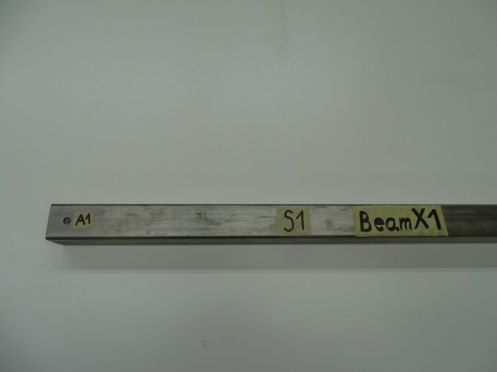
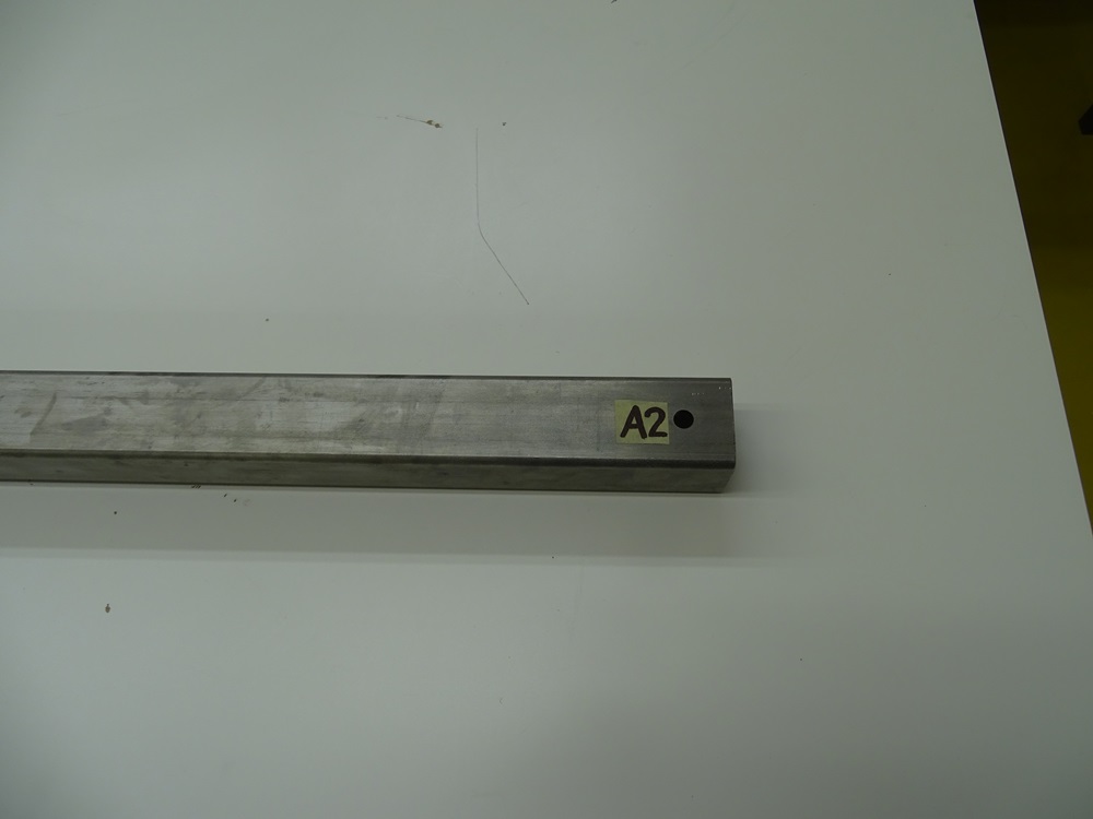
For the Beam X1 drill two 8 mm holes through both sides of the profile on surface S1 and S3. Holes A1 and A2 are in the center of the profile transversely and 20 mm longitudinally from the end edges.
Step 4
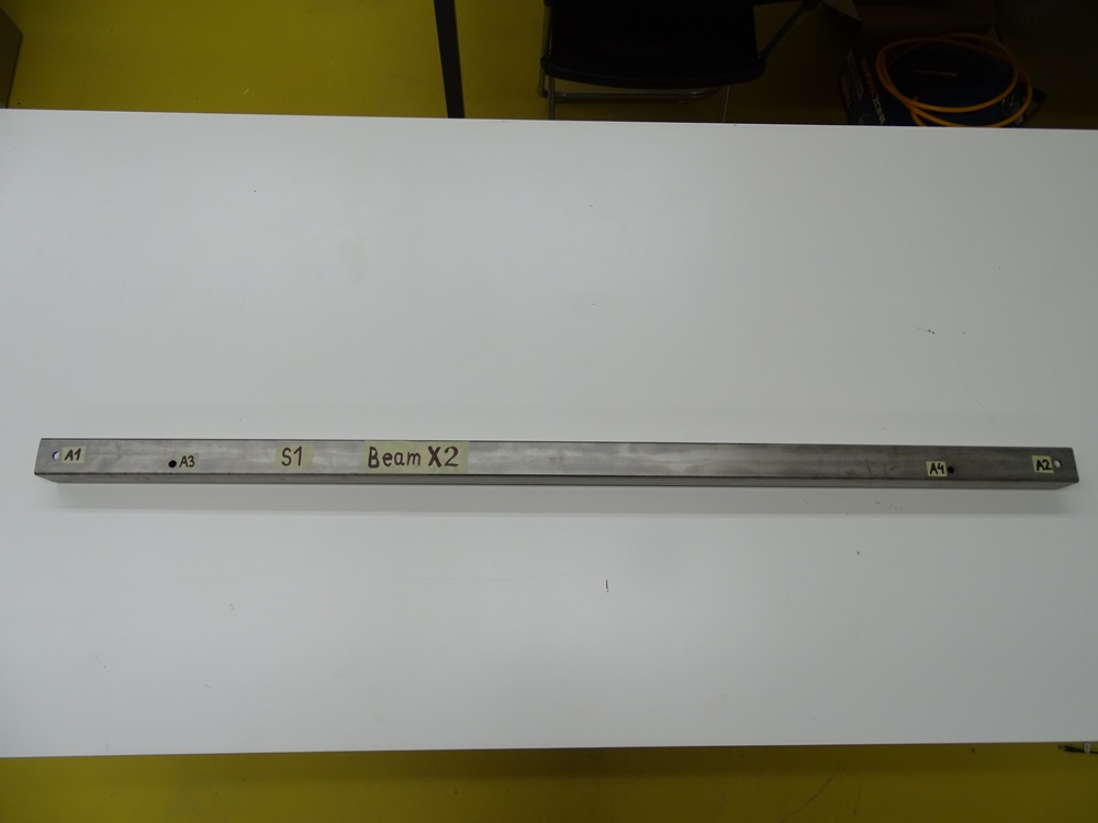
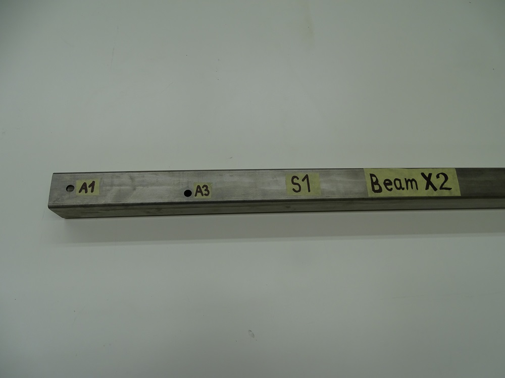
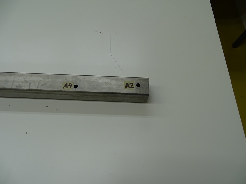
For the Beam X2 drill four 8 mm holes through both sides of the profile on surface S1 and S3. Holes A1 and A2 are transversely in the center of the profile and longitudinally 20 mm from the end edges. Holes A3 and A4 are longitudinally 140 mm and transversely 28 mm from profile edges
Step 5
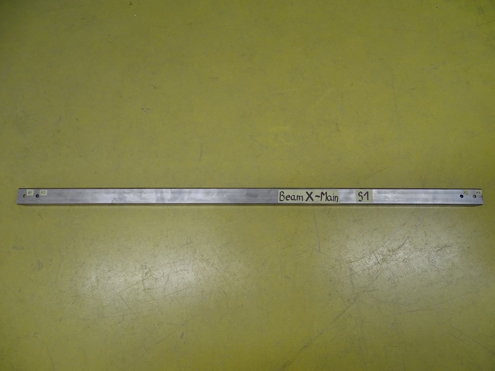
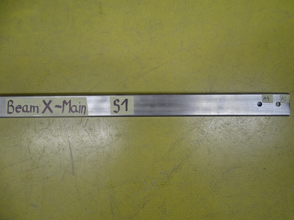
For the Beam X – Main drill four 8 mm holes through both sides of the profile on surface S1 and S3. Transversely all of the holes are in the center of the profile. A1 is 20 mm from end edge and A3 is 30 mm apart from A1. A2 and A4 are symmetrical to A1 and A3.
Updated less than a minute ago
