Trolley assembly
Step 1
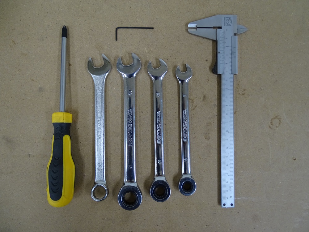
In the picture there are all the necessary tools for Trolley assembly.
Tools needed:
- Phillips screwdriver
- Spanners - sizes: two 13, 10, 8
- Allen key - size: 1.5
- Caliper
Step 2
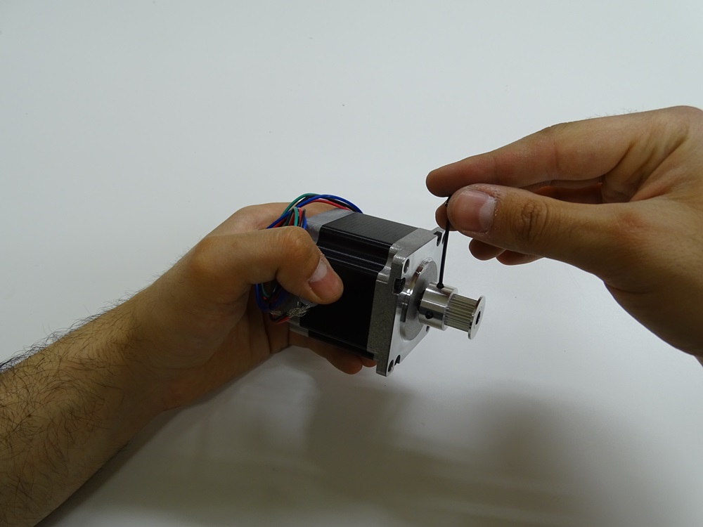
Take NEMA 23 Stepper motor and mount timing pully onto the motor axis. Distance between the motor casing and the timing pully edge should be around 1 mm.
Parts needed
- 3 x NEMA 23 Stepper motor
- 3 x HTD3M/16-10mm timing pulley
Step 3
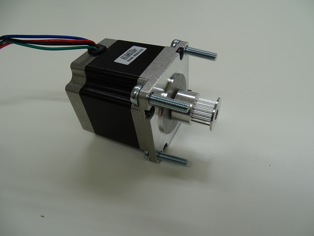
Put DIN 7985 M5x25 bolts into the mounting holes of NEMA 23 Stepper motor. Use washers.
Parts needed
- 4 x DIN 7985 M5x25 bolt
- 4 x DIN 125 5.3
Step 4
Screw the two DIN 934 M5 hex nuts onto each DIN 7985 M5 x 25 bolt, which will serve as the spacers between the stepper and the Front surface of the short Beam Short.
Parts needed:
- 4 x DIN 934 M5 hex nut
Step 5
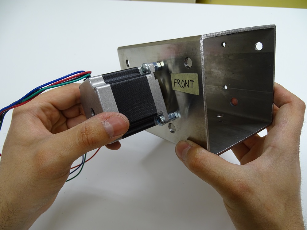
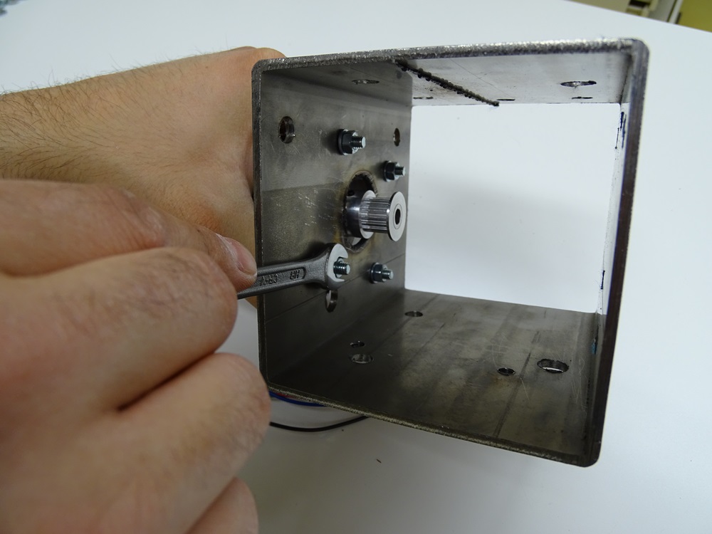
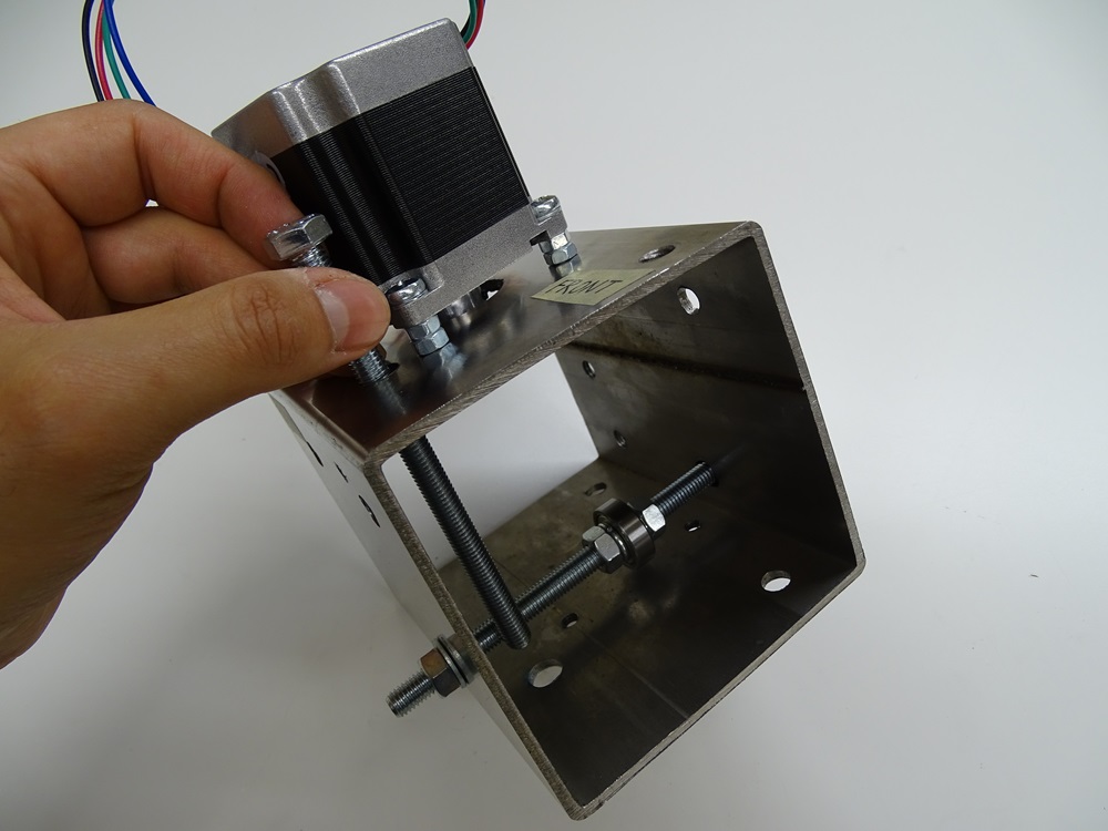
Screw the NEMA 23 Stepper motor onto the Front surface of the Beam Short with four DIN 125 5.3 washers and four DIN 934 M5 hex nuts.
Parts needed:
- 4 x DIN 934 M5 hex nut
- 4 x DIN 125 5.3 washer
Step 6
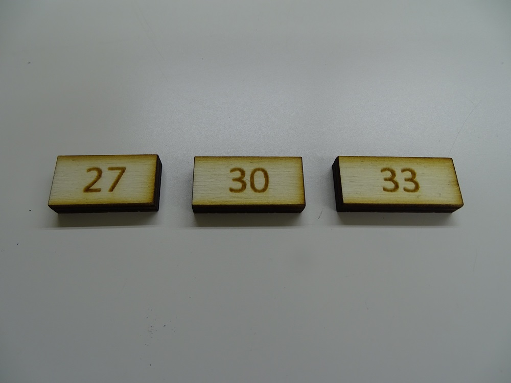
Cut a peace of steel, wood or aluminum 33, 30 and 27 mm long and about 10 mm wide. This will be used as a ruler for measuring distance between the bearing and the inner wall of Beam Short.
Step 7
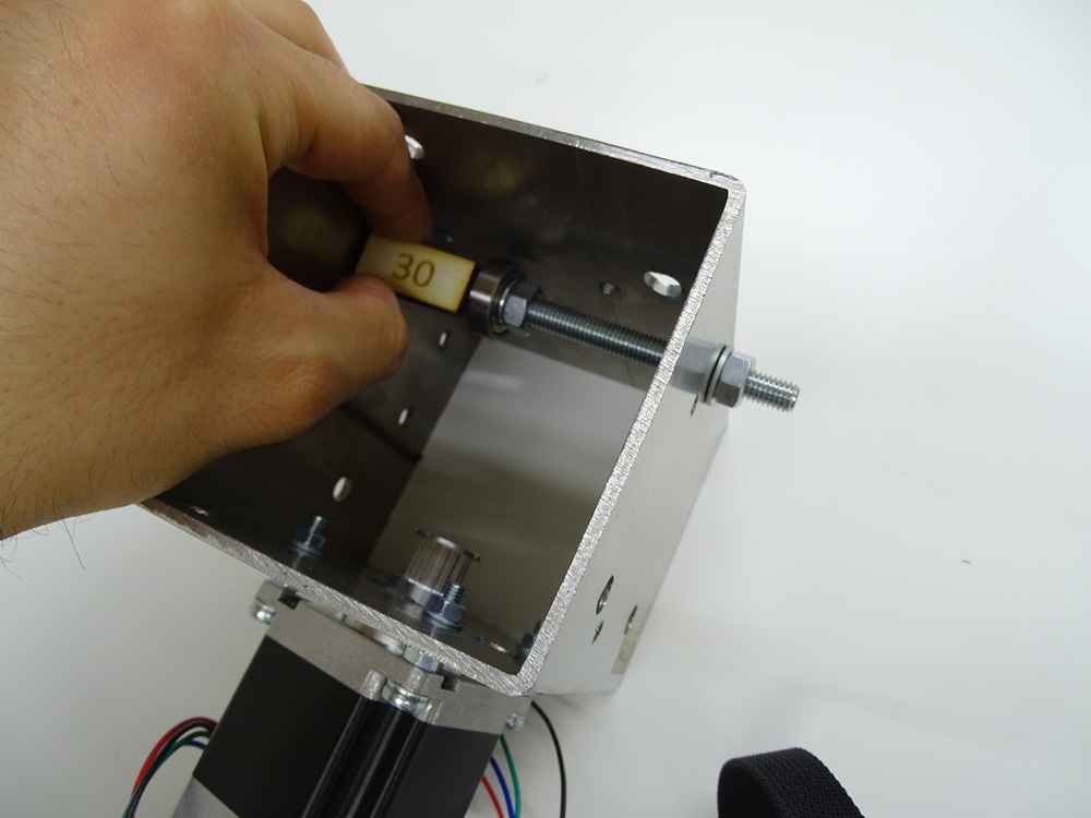
Put the bolt DIN 933 M8 x 120 into B1 hole on the Top surface of Beam Short and screw on the Bearing 608ZZ using hex nuts DIN 934 M8 with spring washers DIN 127 8.5. Distance from the inner top surface to bearing should be 30 mm. Measure the distance with the ruler made in step 6. Screw the nut with a washer on bolt into the Bottom surface.
Parts needed:
- 1 x DIN 933 M8 x 120 bolt
- 3 x DIN 934 M8 hex nut
- 2 x DIN 127 8.5 spring washer
- 1 x DIN 125 8.4 washer
- 1 x 608ZZ bearing
Step 8
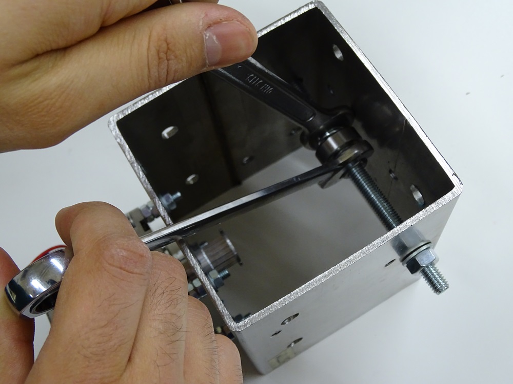
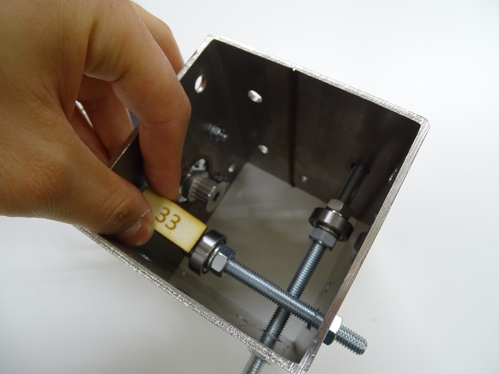
Put the bolt DIN 933 M8 x 120 into the B1 hole on front surface and repeat procedure from step 7. The distance from the inner front surface to bearing should be 33 mm.
Parts needed:
- 1 x DIN 933 M8 x 120 bolt
- 3 x DIN 934 M8 hex nut
- 2 x DIN 127 8.5 spring washer
- 1 x DIN 125 8.4 washer
- 1 x 608ZZ bearing
Step 9
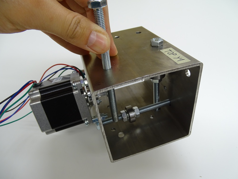
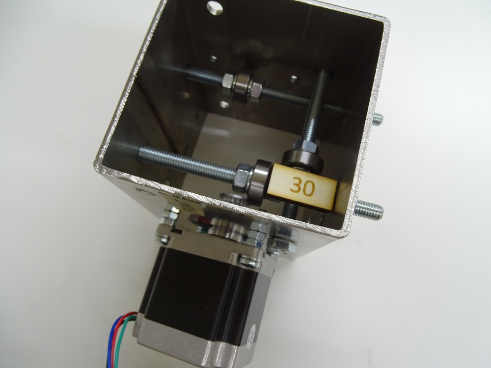
Put the bolt DIN 933 M8 x 120 into A2 hole on the top surface and repeat procedure from step 7. The distance from the inner bottom surface to bearing should be 30 mm.
Parts needed:
- 1 x DIN 933 M8x120 bolt
- 3 x DIN 934 M8 hex nut
- 2 x DIN 127 8.5 spring washer
- 1 x DIN 125 8.4 washer
- 1 x 608ZZ bearing
Step 10
Put the bolt DIN 933 M8 x 120 into A1 hole on the top surface and repeat procedure from step 7. The distance from the inner bottom surface to bearing should be 30 mm.
Parts needed
- 1x DIN 933 M8x120 bolt
- 3x DIN 934 M8 hex nut
- 2x DIN 127 8.5 spring washer
- 1x DIN 125 8.4 washer
- 1x 608ZZ bearing
Step 11
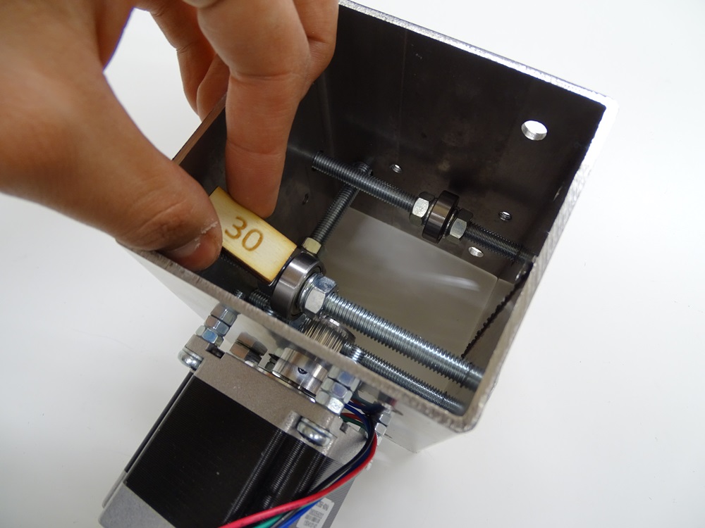
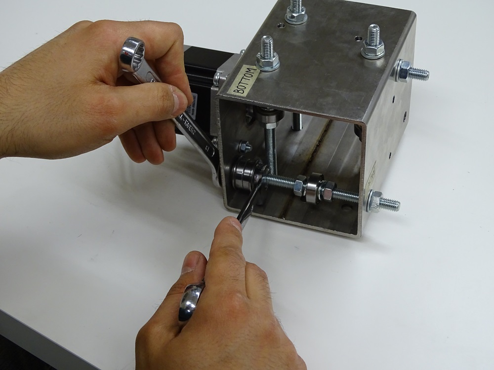
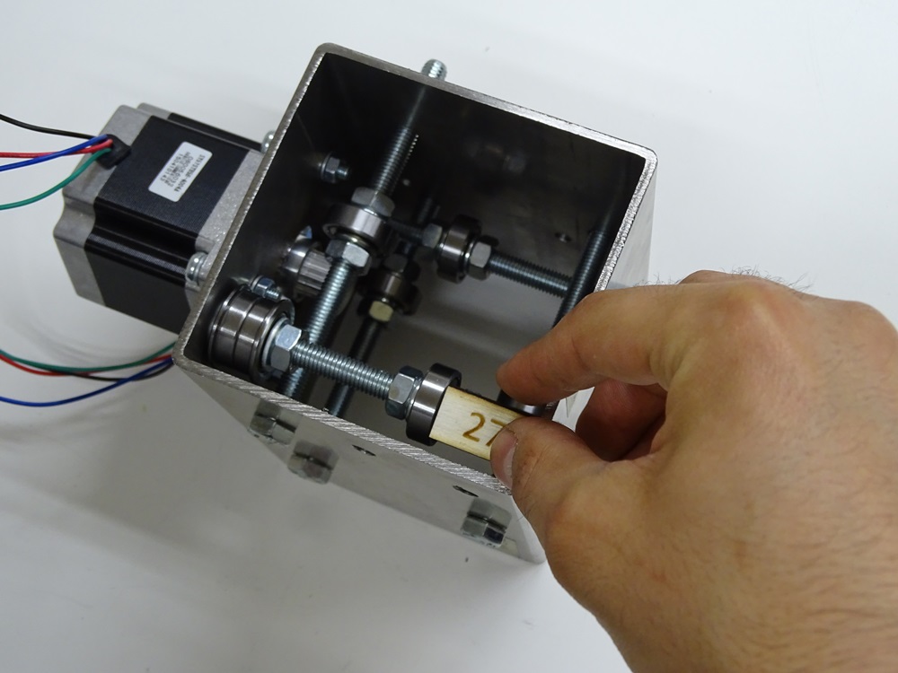
Put the bolt DIN 933 M8x120 into A1 hole on the front surface and put the components on in this order: washer DIN 125 8.4, two Bearings F608Z opposite to each other, washer DIN 125 8.4 and M8 hex nut. Then screw on the Bearing 608ZZ using two hex nuts DIN 934 M8 with two spring washers DIN 127 8.5. The distance from the inner back surface to the bearing should be 27 mm.
Parts needed:
- 1 x DIN 933 M8 x 120 bolt
- 4 x DIN 934 M8 hex nut
- 3 x DIN 125 8.4 washer
- 2 x DIN 127 8.5 spring washer
- 2 x F608Z bearing
- 1 x 608ZZ bearing
Step 12
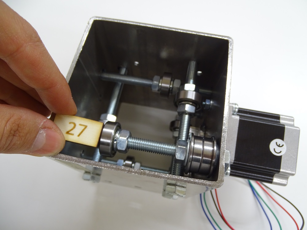
Put the bolt DIN 933 M8 x 120 into A2 hole on the front surface and repeat the procedure from step 11. The distance from the inner back surface to the bearing should be 27 mm.
Parts needed:
- 1 x DIN 933 M8x120 bolt
- 4 x DIN 934 M8 hex nut
- 3 x DIN 125 8.4 washer
- 2 x DIN 127 8.5 spring washer
- 2 x F608Z bearing
- 1 x 608ZZ bearing
Step 13
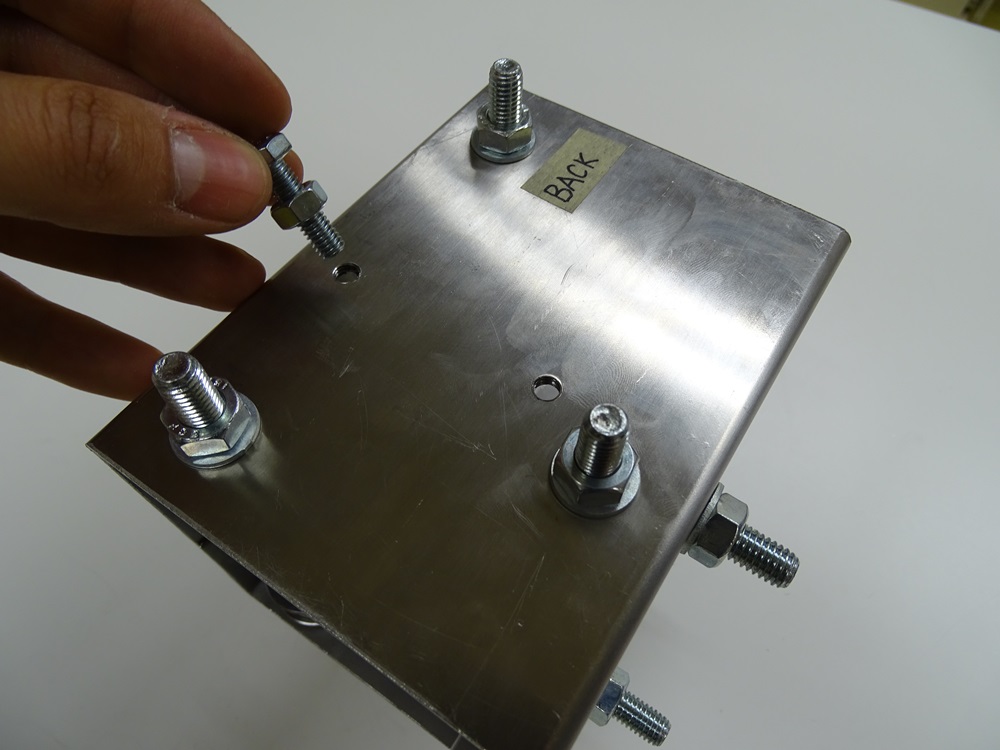
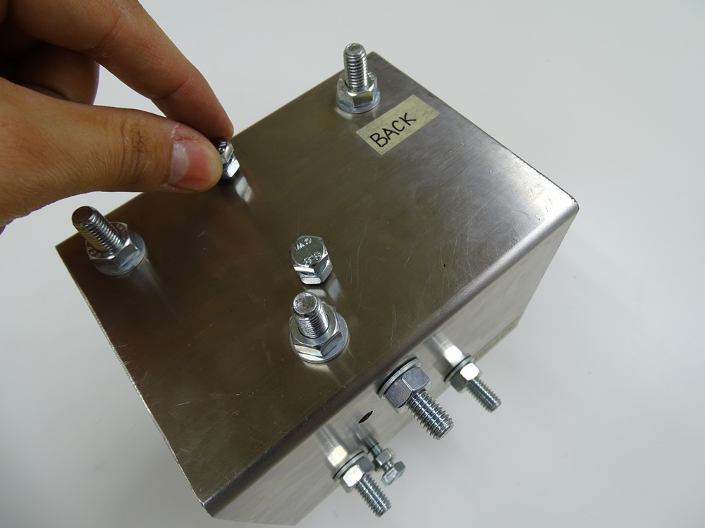
Screw in the two DIN 933 M6x25 bolts in the holes C1 and C2 on the Back surface with DIN 934 M6 hex nuts already screwed on them. Screw them half way in.
Parts needed:
- 2 x DIN 933 M6x25 bolt
- 2 x DIN 934 M6 hex nut
Step 14
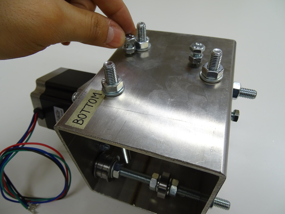
In the holes C1 and C2 on the Bottom surface screw in two DIN 933 M6x25 in the same way as in step 11.
Parts needed:
- 2 x DIN 933 M6 x 25 bolt
- 2 x DIN 934 M6 hex nut
Step 15
Step 16
Instructions for the assembly of the Trolley X are the same, except the following differences.
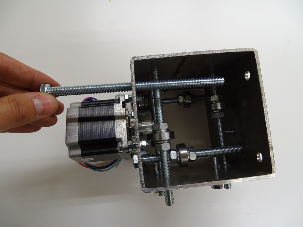
Instead of putting two DIN 933 M8x120 bolts in the holes A1 and A2 on the Front surface, insert two DIN 933 M8x140 bolts. Then, instead of putting DIN 933 M8x120 bolt in the hole B1 on the Front surface, insert DIN 933 M8x110 bolt.
Parts needed
- 2 x DIN 933 M8 x 140 bolt
- 1 x DIN 933 M8 x 110 bolt
Step 17
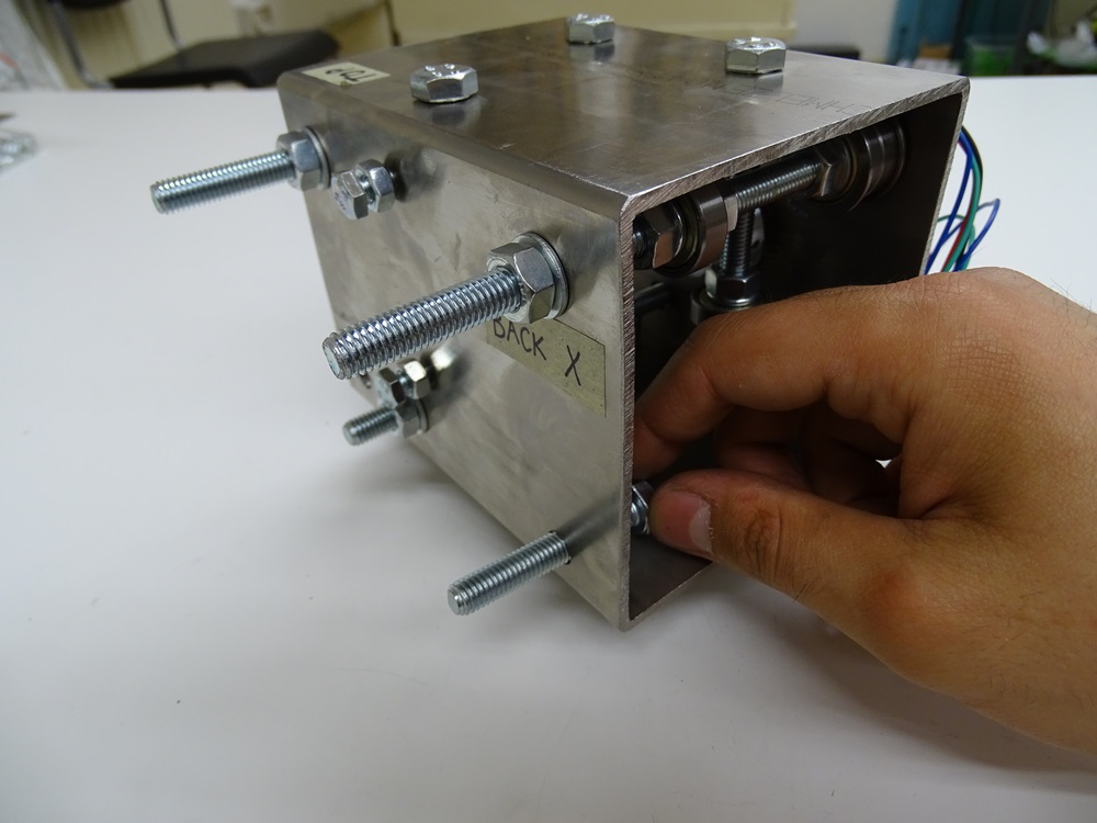
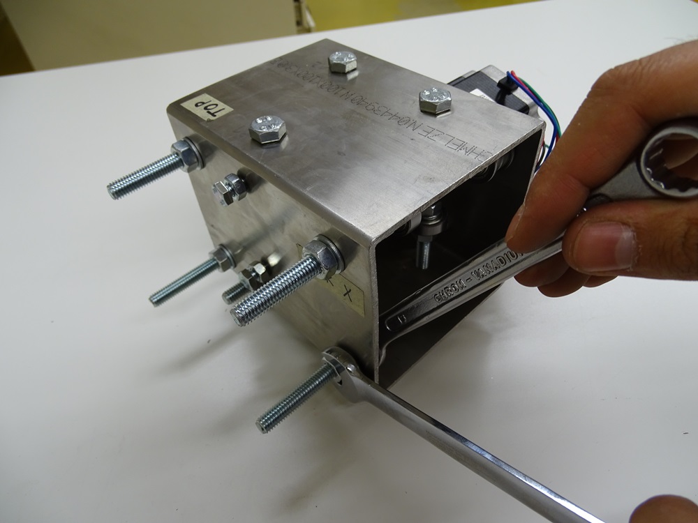
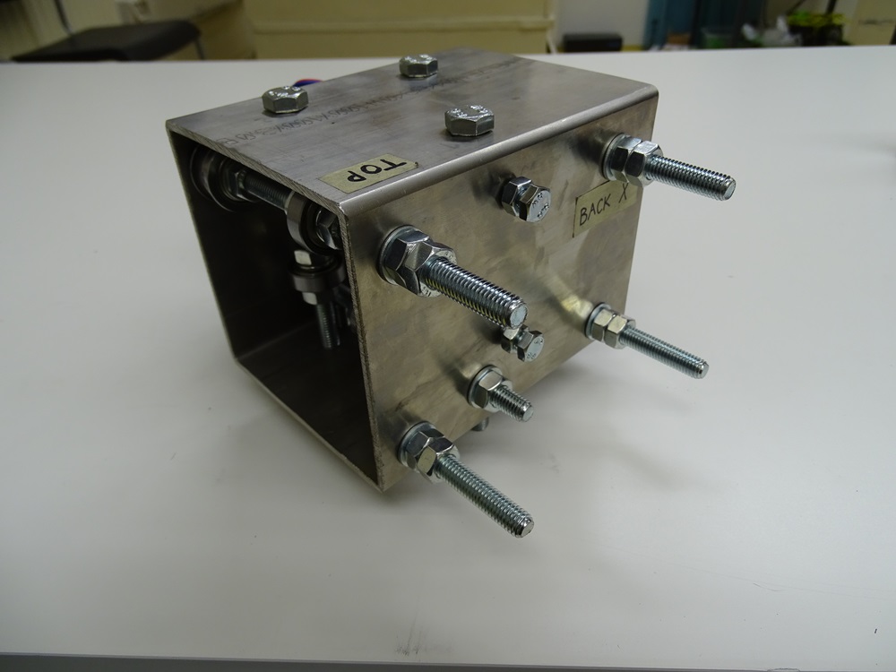
Put two DIN 933 M8x50 bolts in holes A3 and A4 from the inner side of the Back surface. Screw two hex nuts DIN 934 M8 with washers DIN 125 8.4 on these bolts onto Back surface. Screw additional four M8 hex nuts on all four bolts that are protruding out of the Back surface. These will serve as spacers between Trolley X and Bearing plate of Z-Axis.
Parts needed:
- 2 x DIN 933 M8 x 50 bolt
- 6 x DIN 934 M8 hex nut
- 2 x DIN 125 8.4 washer
Step 18
Great!
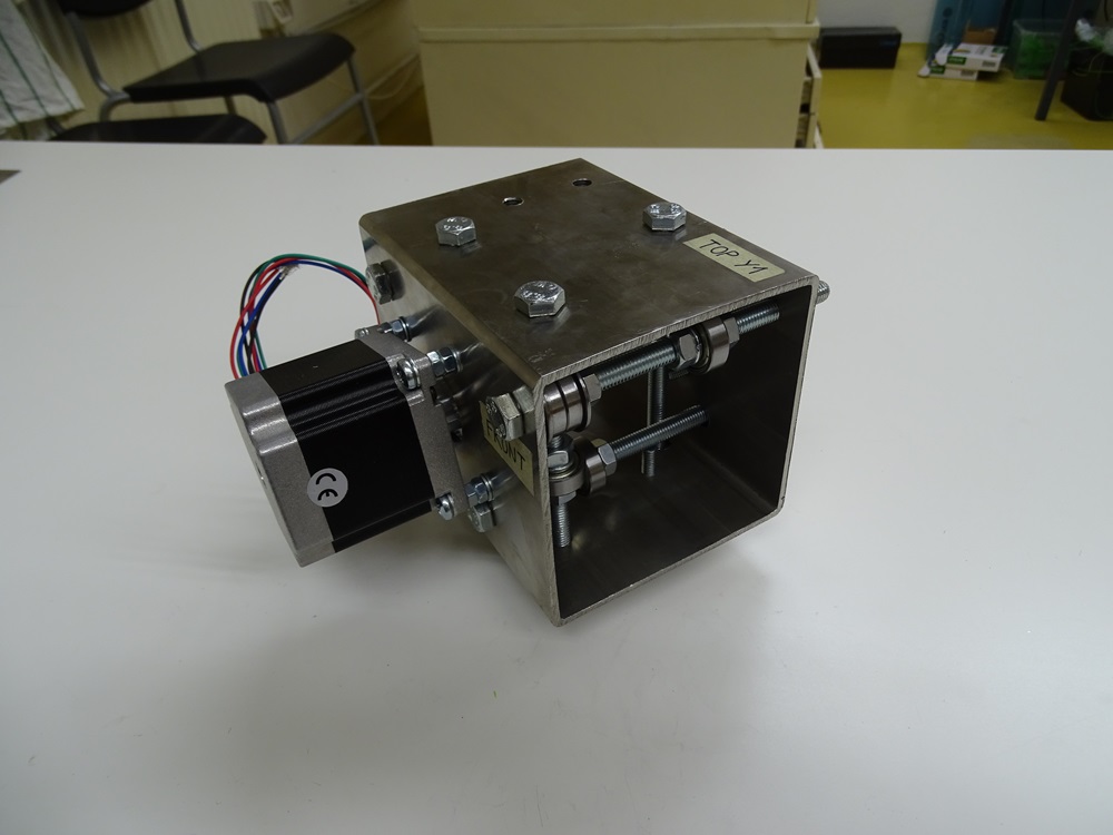
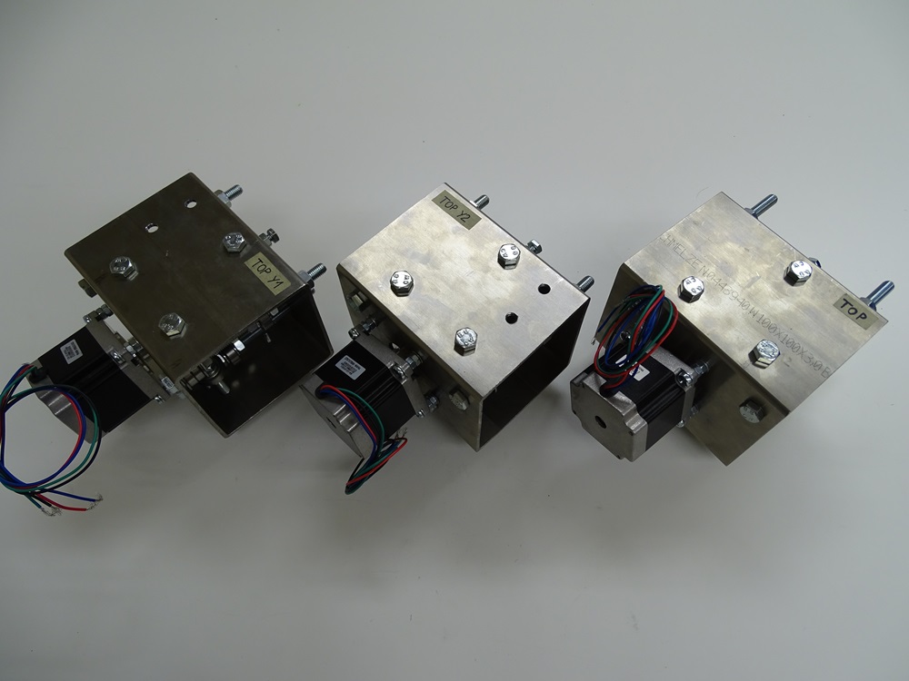
Your trolleys are ready for the final assembly.
Updated less than a minute ago
