Z axis assembly
Step 1
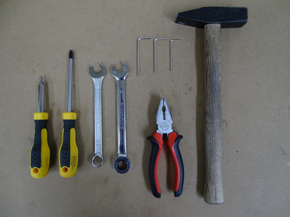
In the picture there are all the necessary tools for Z Axis assembly.
Tools needed:
- Torx screwdriver - size: T10
- Phillips screwdriver
- Spanners - sizes: two 13
- Allen keys - sizes: 2, 2.5, 3
- Pliers
- Hammer
Step 2
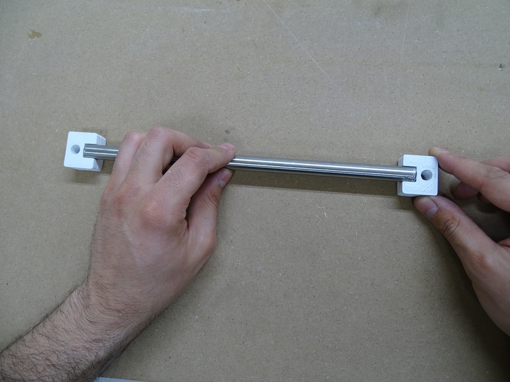
Put 12 mm round rod (270 mm in length) into round notch on printed part Linear guide mount. Do this on both ends of the rod. Make sure that the orientation of the linear guide mounts is the same.
Repeat the step for the second rod
Parts needed:
- 2 x 12 x 270 mm round rod
- 4 x Linear guide mount
Step 3
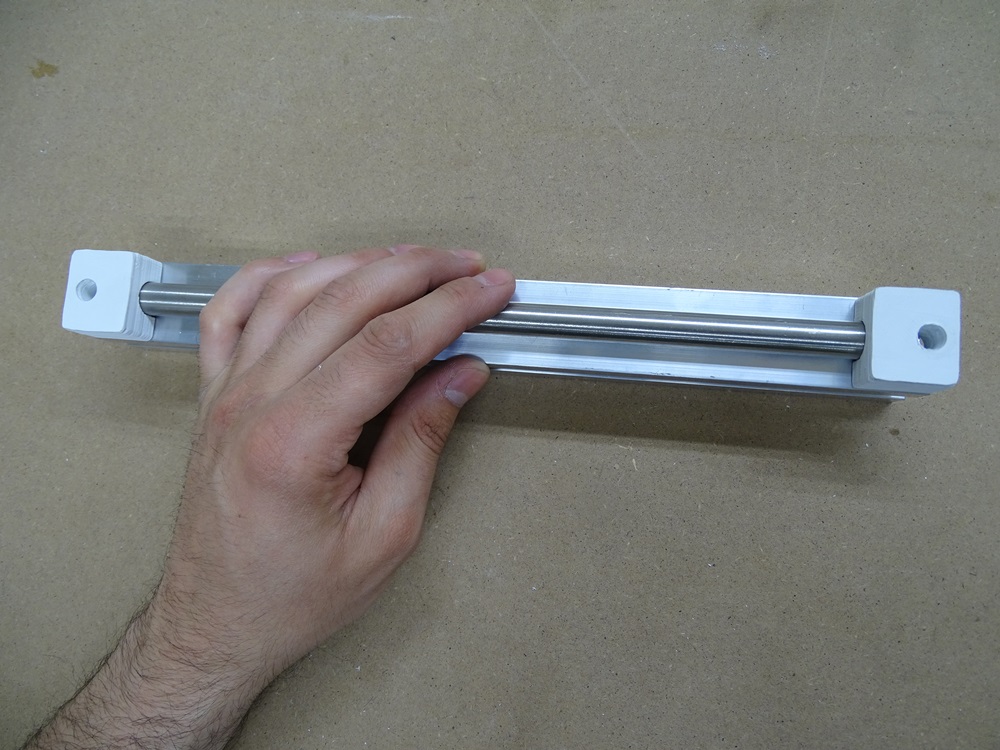
Put this rod into the groove on aluminium X profile.
Repeat for the other rod.
Parts needed:
- 2 x 300 mm X profile
Step 4
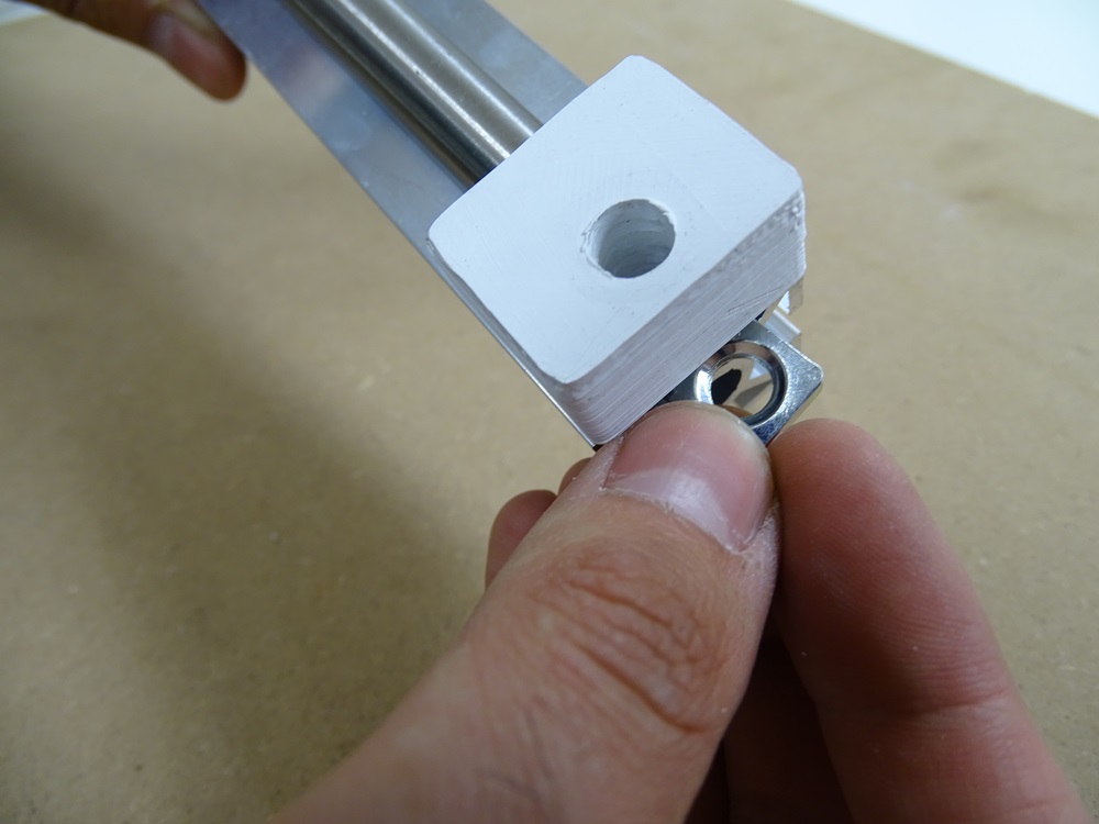
Put the square nut DIN 562 M8 into the groove on X profile below the linear guide mounts as shown in the picture. Do this on both ends of the profile.
Repeat.
Parts needed:
- 4 x DIN 562 M8 square nut
Step 5
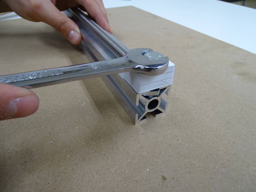
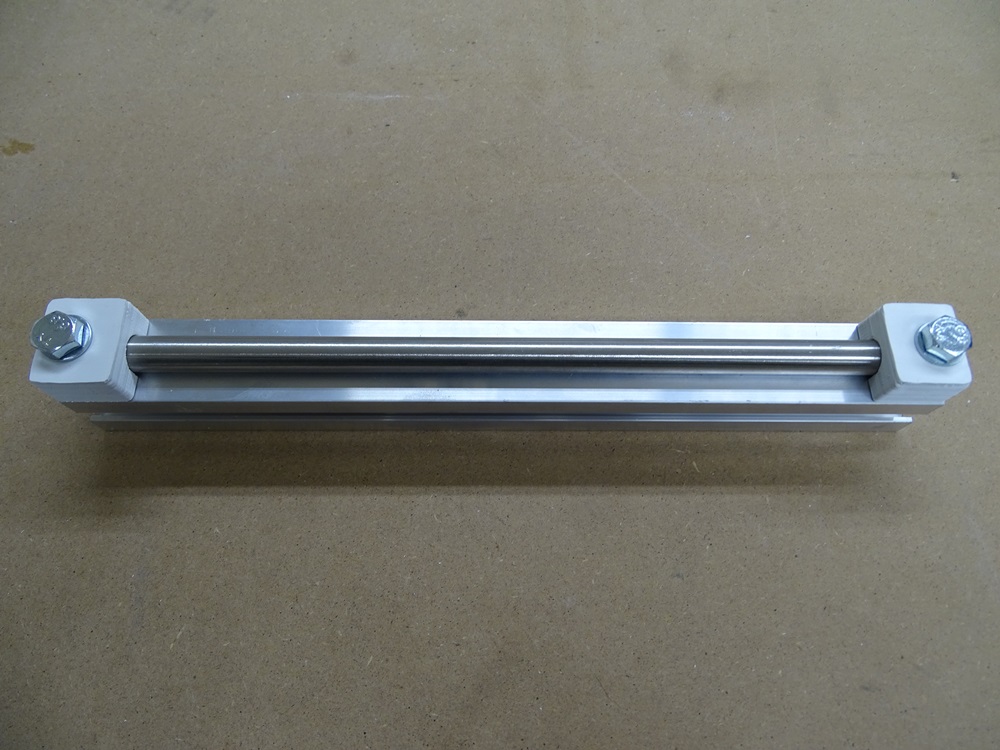
Screw in DIN 933 M8x25 bolt through the Linear guide mount into M8 square nut. Because of the shape, the square nut does not rotate and we can fasten the bolt firmly. Use DIN 125 8.4 washers. Do this on both ends of the profile.
Repeat the steps ont he other profile.
Parts needed
- 4 x DIN 933 M8 x 25 bolt
- 4 x DIN 125 8.4 washer
Step 6
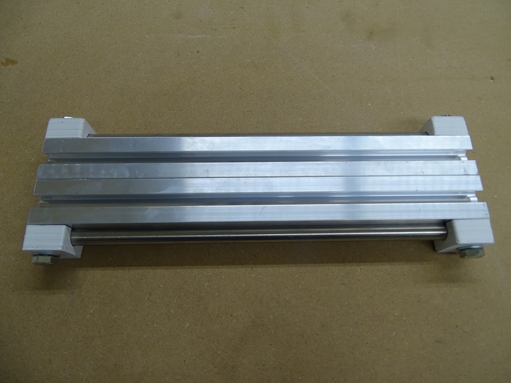
Put both completed assemblies together as shown in the picture.
Step 7
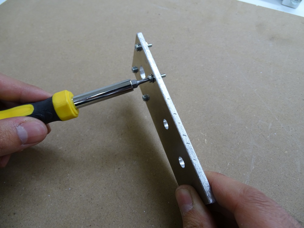
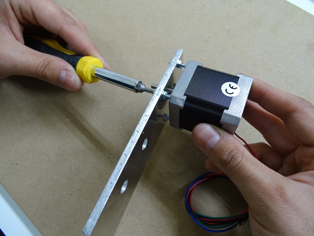
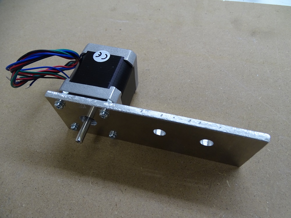
Take Motor plate and put four ISO 14583 M3 x 12 torx bolts into four 3 mm (A1, A2, A3, A4) holes. Use DIN 125 3.2 wahsers. Screw the bolts with four DIN 934 M3 hex nuts.
Parts needed:
- 1 x Motor plate
- 4 x ISO 14583 M3 x 12 torx bolt
- 4 x DIN 125 3.2 wahser
- 4 x DIN 934 M3 hex nut
Step 8
Fasten the NEMA 17 Stepper motor onto the Motor plate with these four torx bolts.
Parts needed:
- 1 x NEMA 17 stepper motor
Step 9
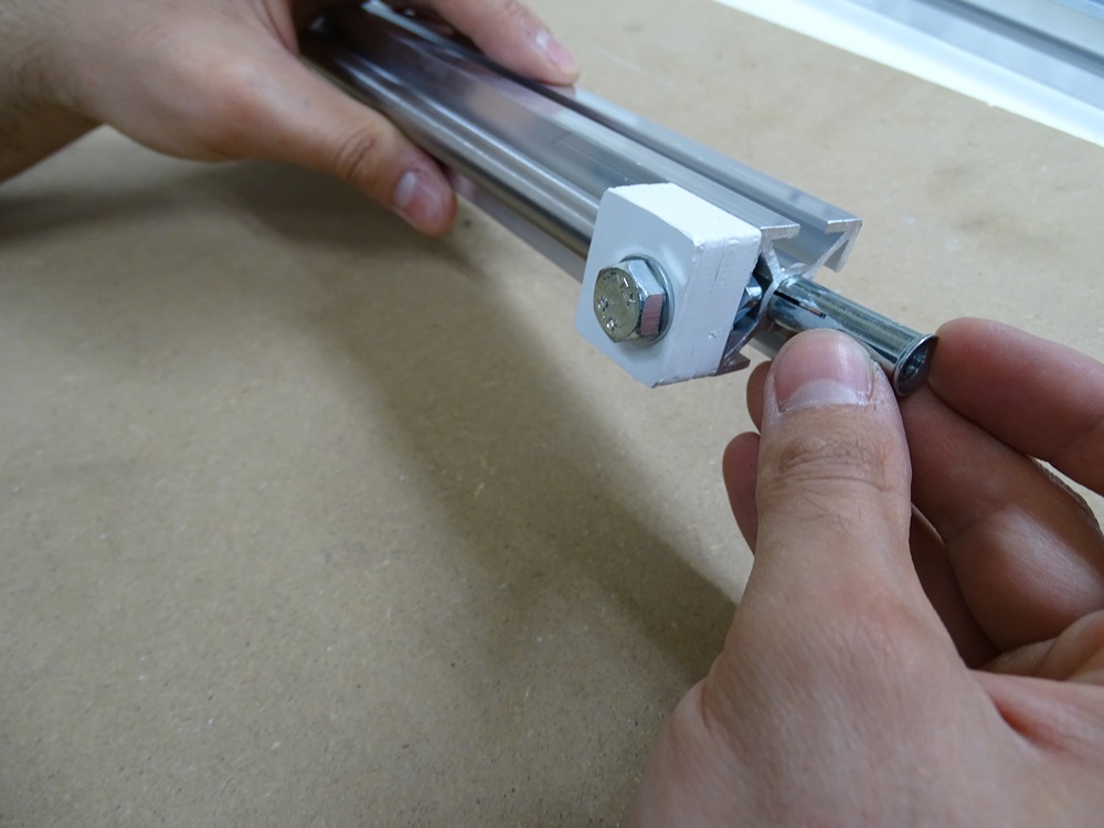
Put two metal 10 mm screw anchors into both center holes on one end of the X profiles.
Parts needed:
- 2 x 10 mm screw anchor
Step 10
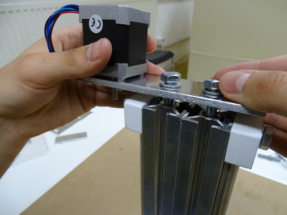
Put the Motor plate with already attached motor onto the assembly and fasten it with two DIN 933 M8 x 16 bolts. Use DIN 125 8.4 washers.
Parts needed:
- 2 x DIN 933 M8 x 16 bolt
- 2 x DIN 125 8.4 washer
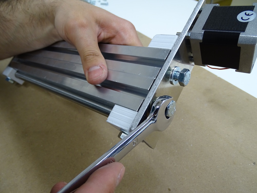
Step 11
Put two plastic 10 mm screw anchors into both center holes on the other end of the X profiles.
Parts needed:
- 2 x 10mm screw anchor
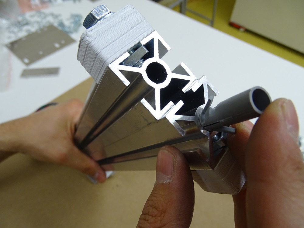
Step 12
Put the Bottom plate on this end of the assembly and fasten it with two DIN 7996 4.5x50 wood cross screws. Use DIN 125 5.3 washers.
Part needed:
- 2 x DIN 7996 4.5 x 50 cross screw
- 2 x DIN 125 5.3 washer
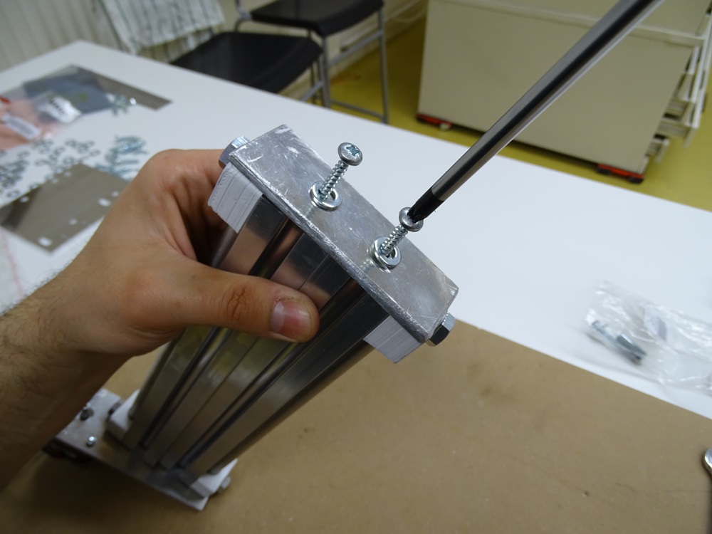
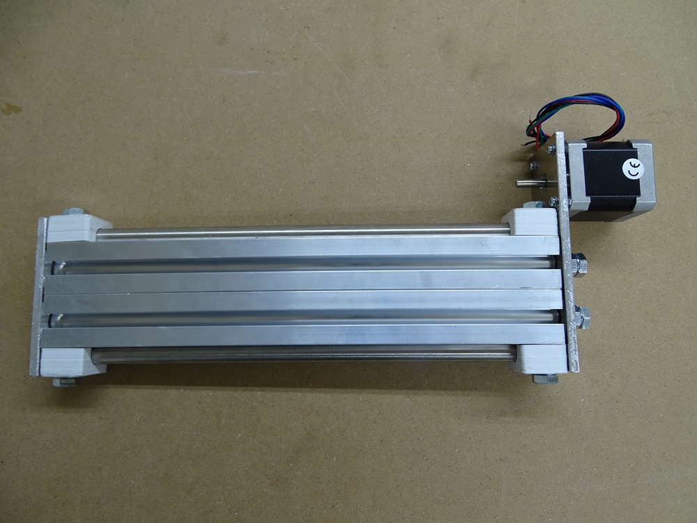
Step 13
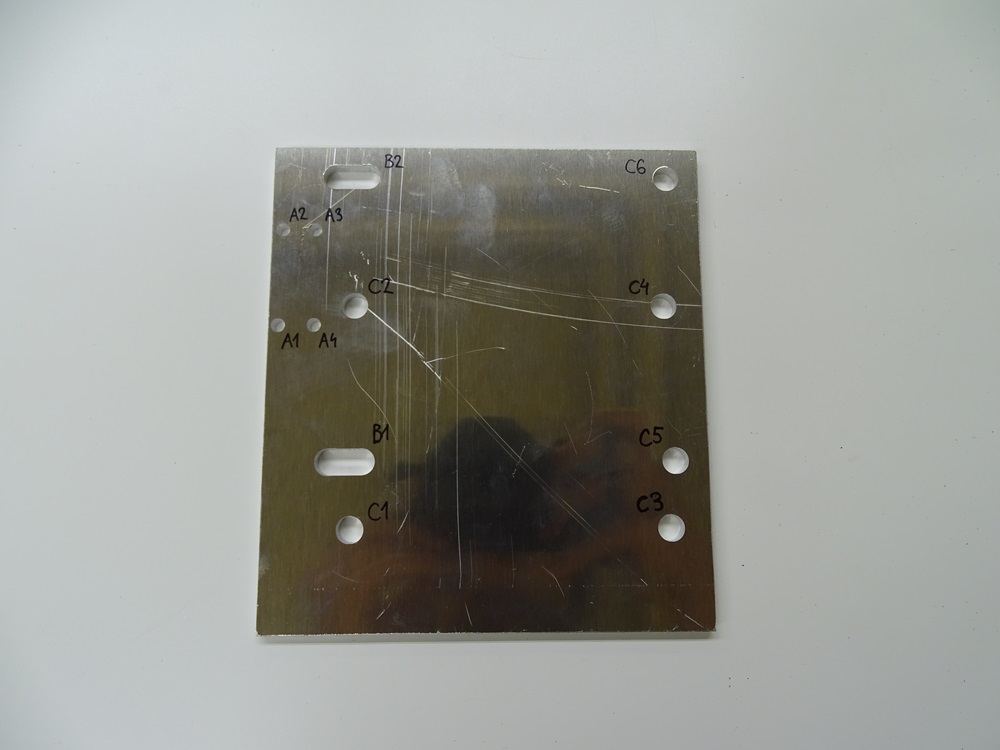
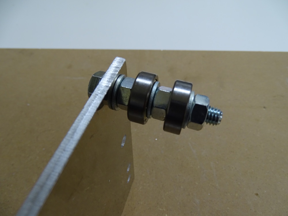
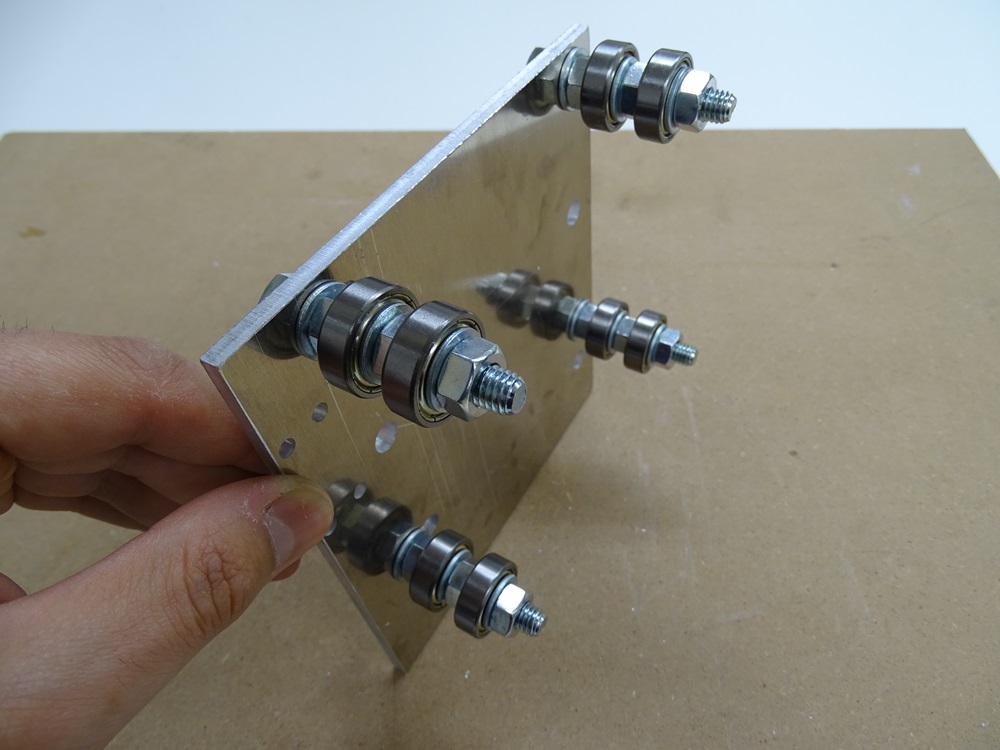
Take Bearing plate and put four DIN 933 M8x50 bolts in the round holes C5, C6 and slot holes B1, B2. Make sure to use DIN 125 8.4 washers also on the back side of the plate. On the front side of the plate put parts on each of these bolts in the following order: washer DIN 125 8.4, hex nut DIN 934 M8, bearing 608ZZ, then again washer DIN 125 8.4, hex nut DIN 934 M8, bearing 608ZZ, and in the end washer DIN 125 8.4 with hex nut DIN 934 M8.
Parts needed:
- 1 x Bearing plate
- 4 x DIN 933 M8 x 50 bolt
- 8 x DIN 934 M8 hex nut
- 16 x DIN 125 8.4 washer
- 8 x 608ZZ bearing
Step 14
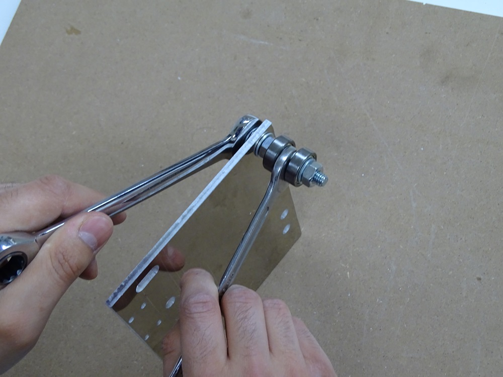
For the bolts in holes C5 and C6 - tighten all the nuts firmly.
For the bolts in slot holes B1 and B2 - do not tighten the nuts too firmly because we must adjust their position precisely in later steps.
Step 15
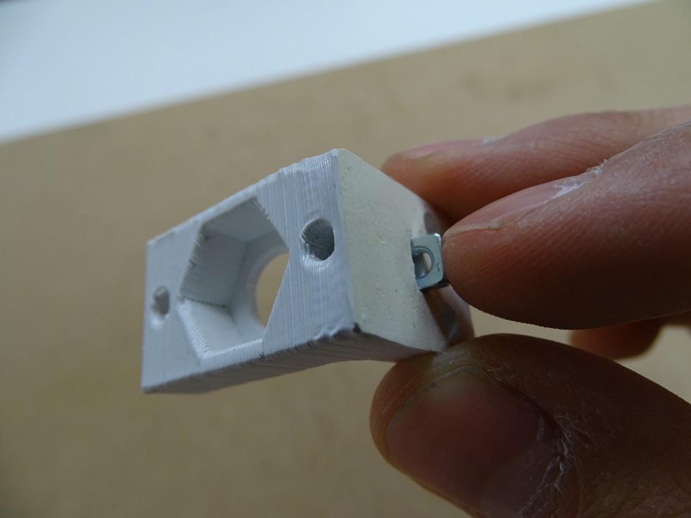
Take printed part Nut casing – Bottom and put DIN 562 M3 square nut into the square slot.
Parts needed:
- 1x Nut casing – Bottom
- 1x DIN 562 M3 square nut
Step 16
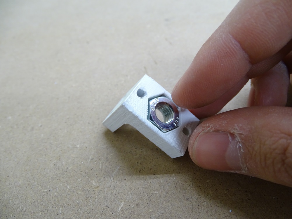
Put DIN 934 M8 hex nut into the hex shaped hole on the part Nut casing – Bottom.
Parts needed:
- 1 x DIN 934 M8 hex nut
Step 17
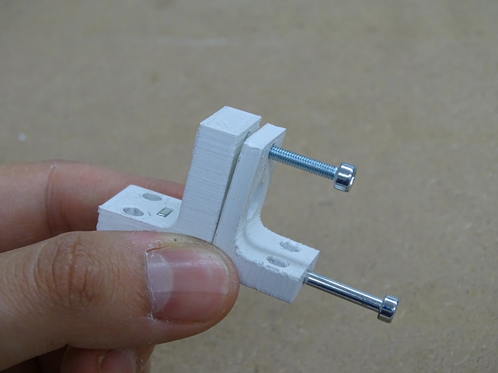
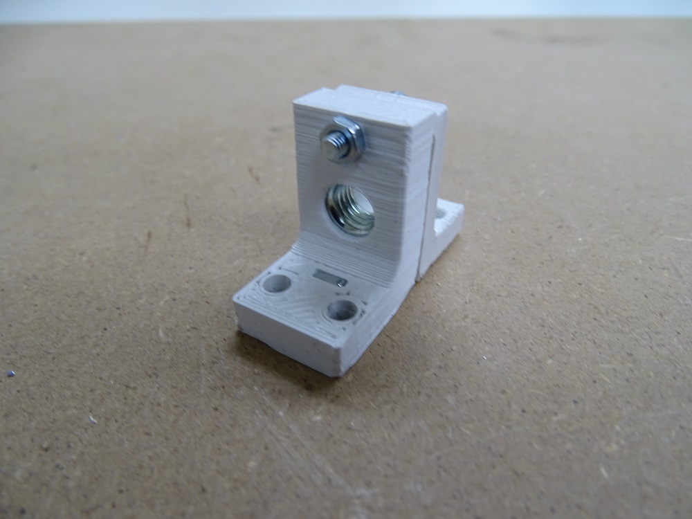
Take parts Nut casing – Bottom nad Nut casing – Upper and put them together as shown on the picture. Put hex socket bolts DIN 912 M3 x 35 and DIN 912 M3 x 16 through 3 mm holes on both parts.
Parts needed
- 1 x Nut casing – Upper
- 1 x DIN 912 M3 x 35 bolt
- 1 x DIN 912 M3 x 16 bolt
Step 18
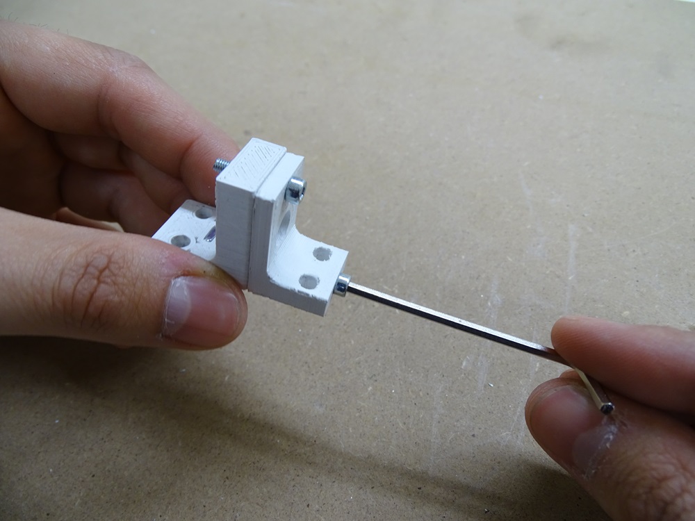
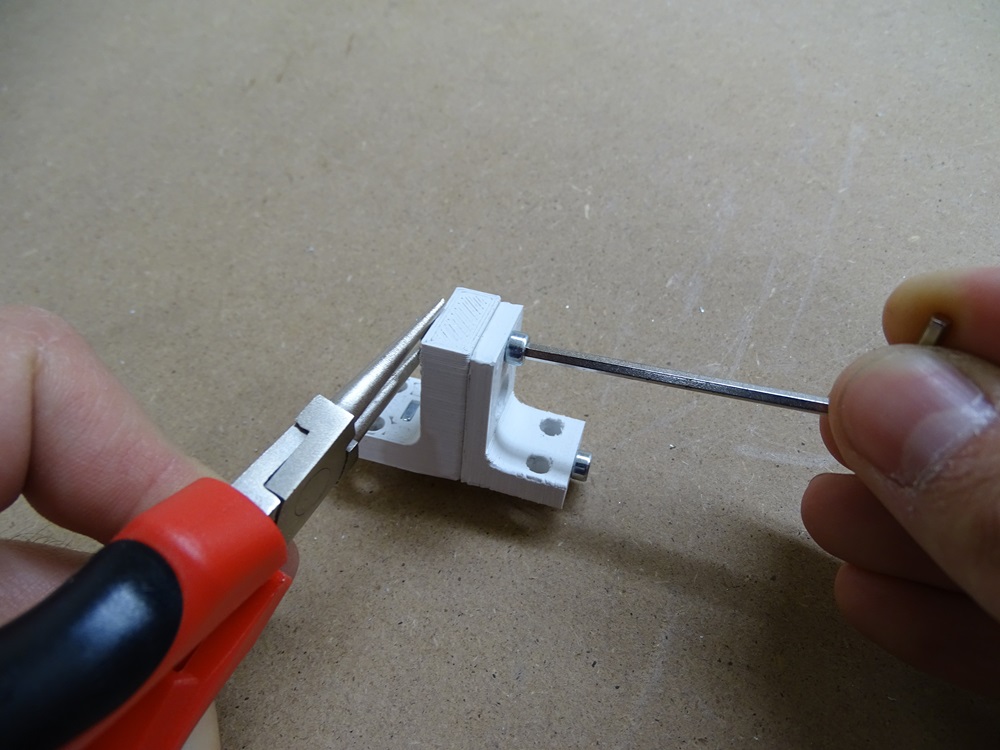
Screw bigger bolt DIN 912 M3 x 35 into M3 square nut which is already inserted in Nut casing – Bottom. Screw smaller DIN 912 M3 x 16 bolt with DIN 934 M3 hex nut.
Parts needed:
- 1 x DIN 934 M3 hex nut
Step 19
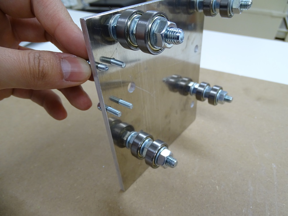
Put four DIN 912 M4 x 16 hex socket bolts in four 4 mm holes (A1, A2, A3, A4).
Parts needed:
- 4 x DIN 912 M4 x 16 bolt
Step 20
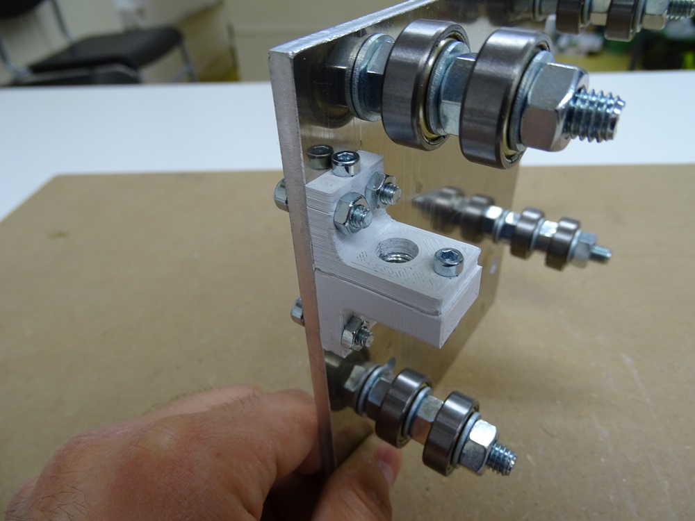
Fasten the Nut casing assembly onto these four bolts with four DIN 934 M4 hex nuts as shown in the picture.
Parts needed:
- 4x DIN 934 M4 hex nut
Step 21
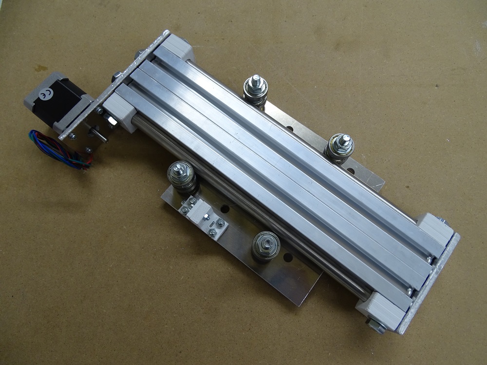
Put assembly with X profiles on bearing plate between bolts with bearings. Make sure that stell round rods are in the middle of two bearings on each bolt.
Step 22
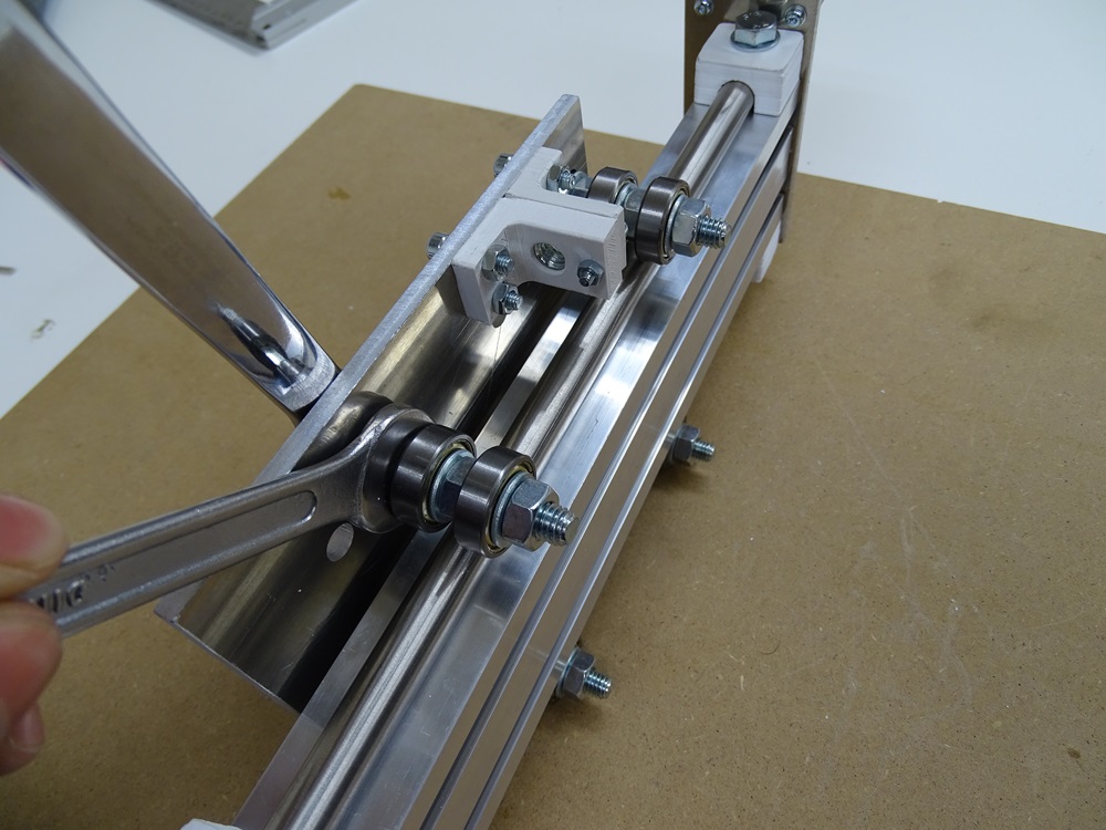
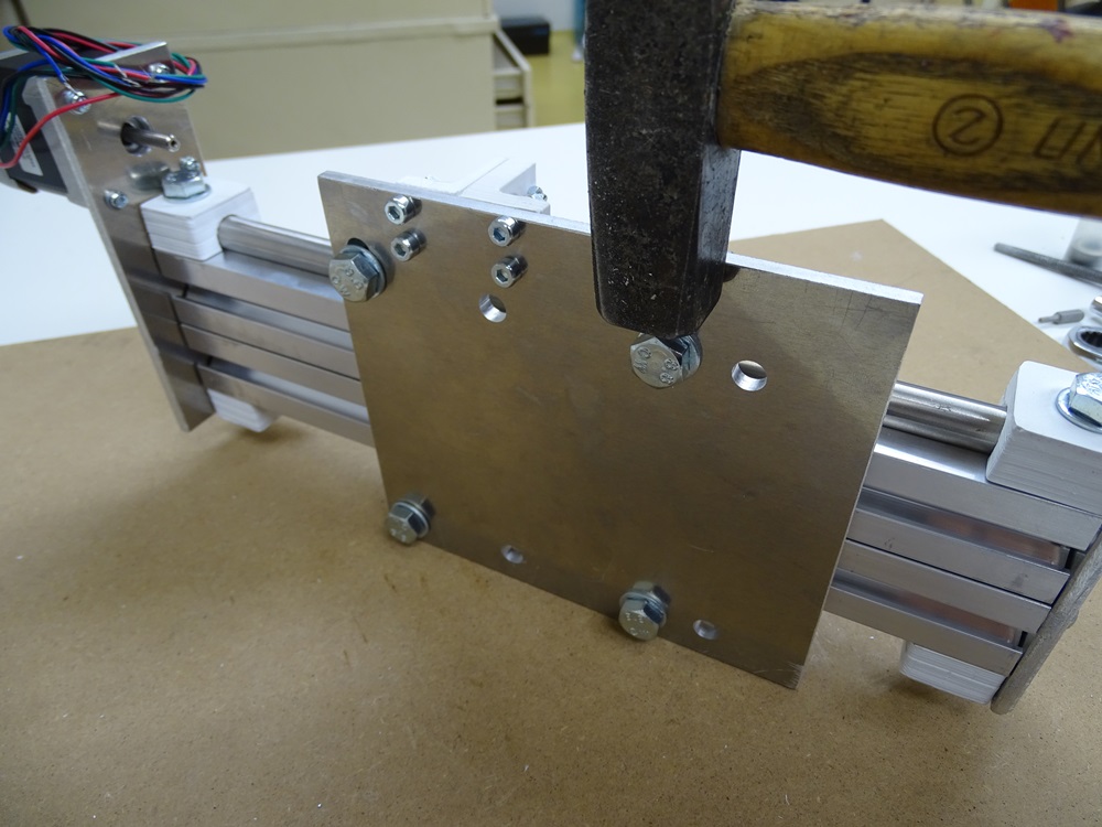
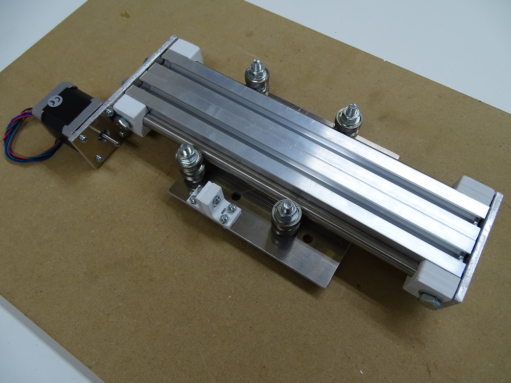
Fasten the nuts on the bolts that are located in the slot holes B1 and B2. It is important that bearings sit tight on the steel round rods, so make sure to press it hard with spanners when fastening the nuts. If all the bearings are not sitting tightly with round rods, then try using a hammer before fastening the nuts firmly.
Step 23
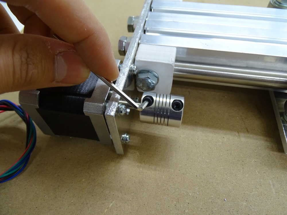
Fasten the Coupler (5 to 8 mm) on motor shaft.
Parts needed:
- 1 x 5-8 mm coupler
Step 24
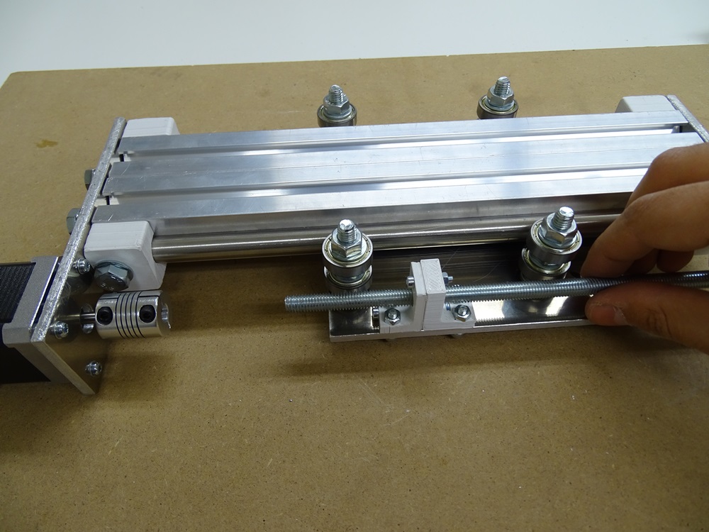
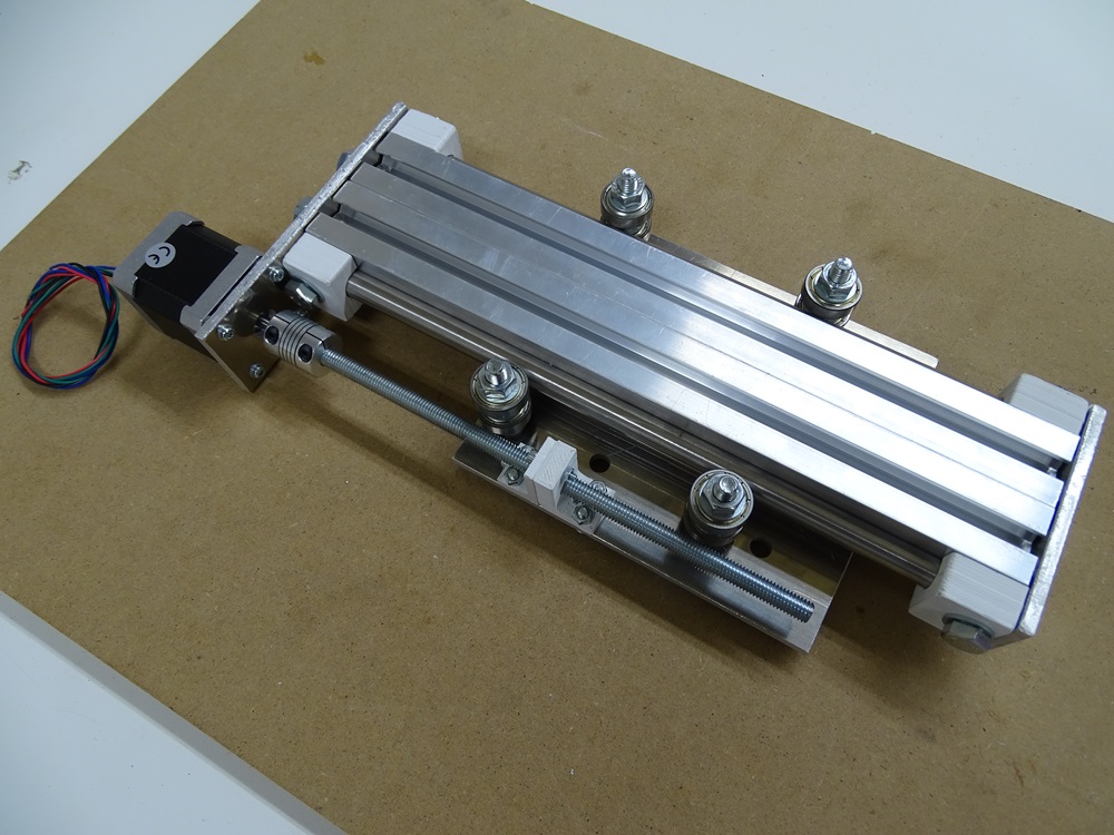
Screw the M8 x 200 threaded rod through the M8 nut in Bearing casing up to the Coupler. Fasten the M8 rod in the 8 mm hole on the other side of the Coupler.
Parts needed:
- 1 x M8 x 200 threaded rod
Step 25
Updated less than a minute ago
