Frame assembly
Step 1
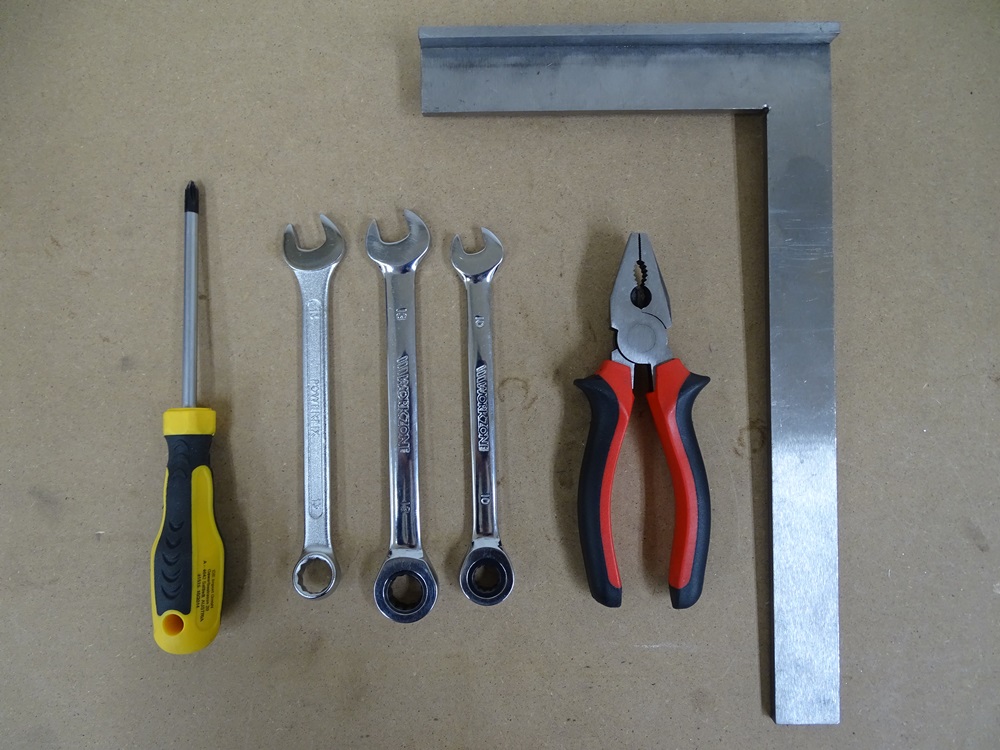
In the picture there are all necessary tools for frame assembly.
Tools needed:
- Phillips screwdriver
- Spanners - sizes: two 13, 10
- Pliers
- Machinist's Square
Step 2
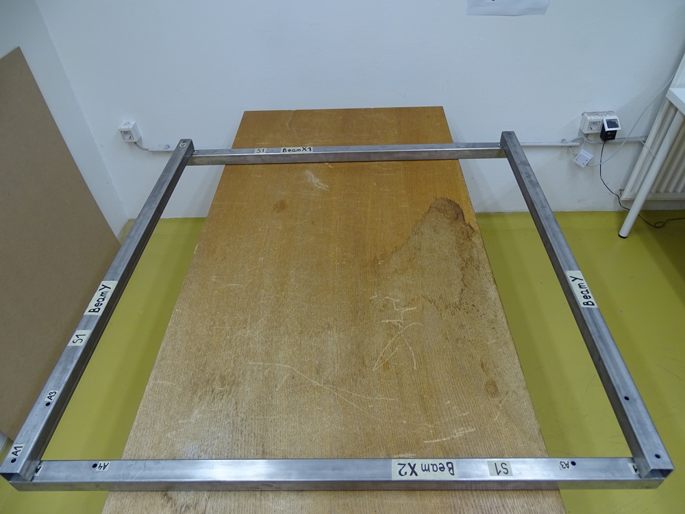
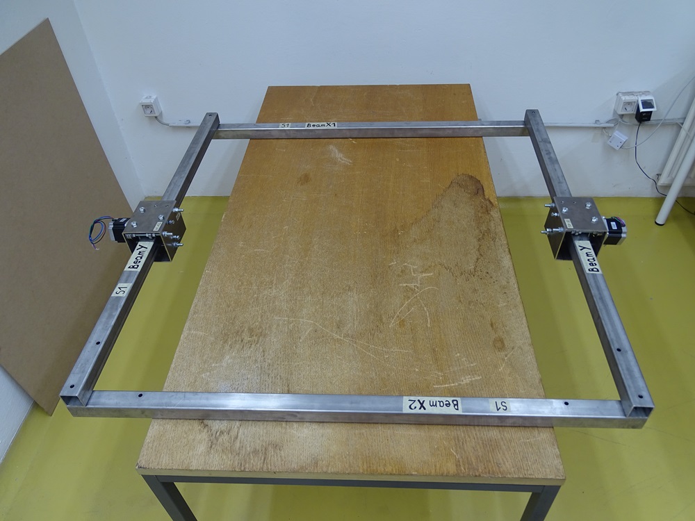
Put the Beam X1 and the Beam X2 onto assembly table approximately 1160mm apart to each other in a fashion that A3 and A4 holes on Beam X2 are facing inwards. Put both Beams Y on the prepared Beams X1 and X2 in a fashion that A3 holes on Beams Y are facing inwards.
Make sure that the holes for mounting Turnbuckle will be in the same corner – see picture.
Parts needed
- 2 x Beam Y
- 1 x Beam X1
- 1 x Beam X2
Step 3
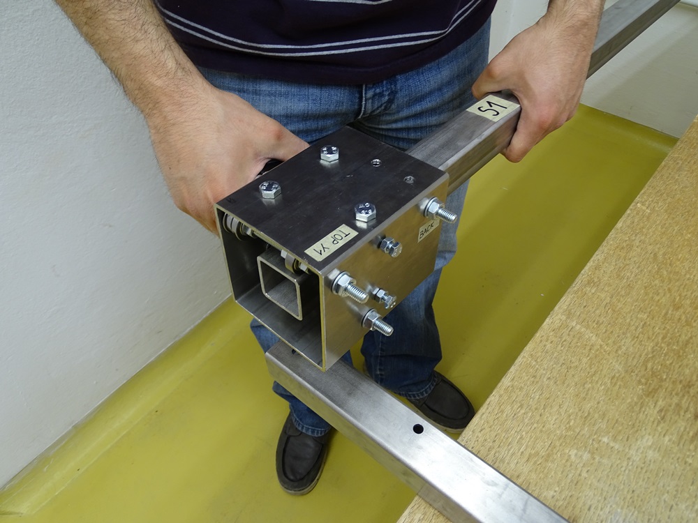
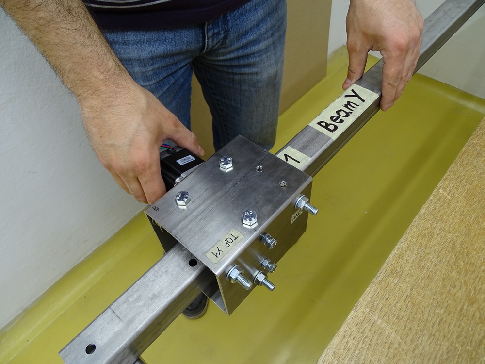
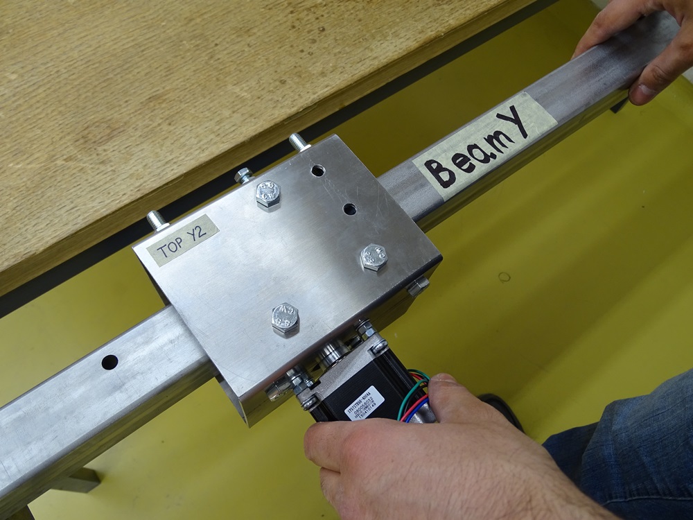
Take Trolley Y1 and Y2 and slide one of them on each Beam Y in a fashion that both motors will be facing outwards.
Parts needed
- 1x Trolley Y1
- 1x Trolley Y2
Step 4
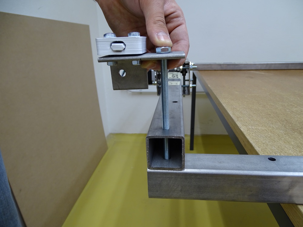
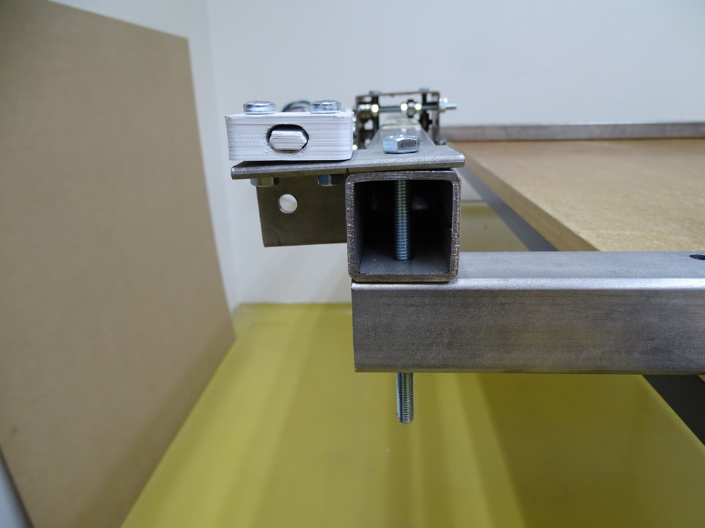
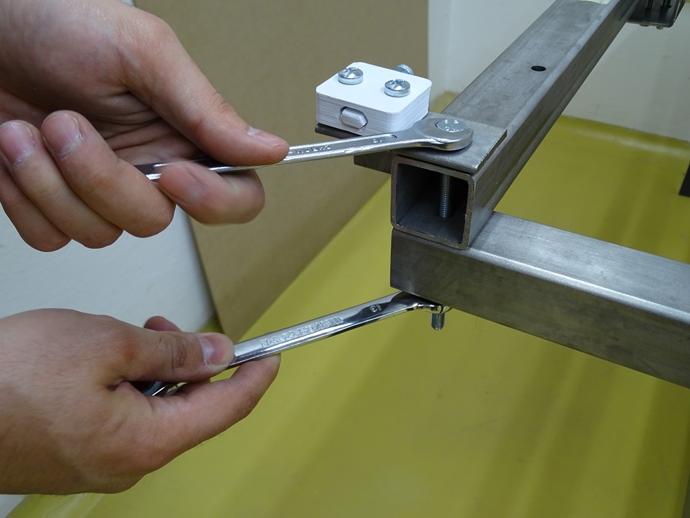
Mount together first corner of the frame with DIN 933 M8x120 bolt, DIN 934 M8 hex nut and DIN 125 8.4 washer. Before screwing, put tightener on the top of the Beam Y. Make sure that Tighteners are facing outwards of the construction and to each other – see picture.
Proceed with screwing the three remaining corners using Tighteners.
Parts needed
- 4x DIN 933 M8x120 bolt
- 4x DIN 934 M8 hex nut
- 4x DIN 125 8.4 washer
- 2x Tightener Assembly - Left
- 2x Tightener Assembly - Right
Step 5
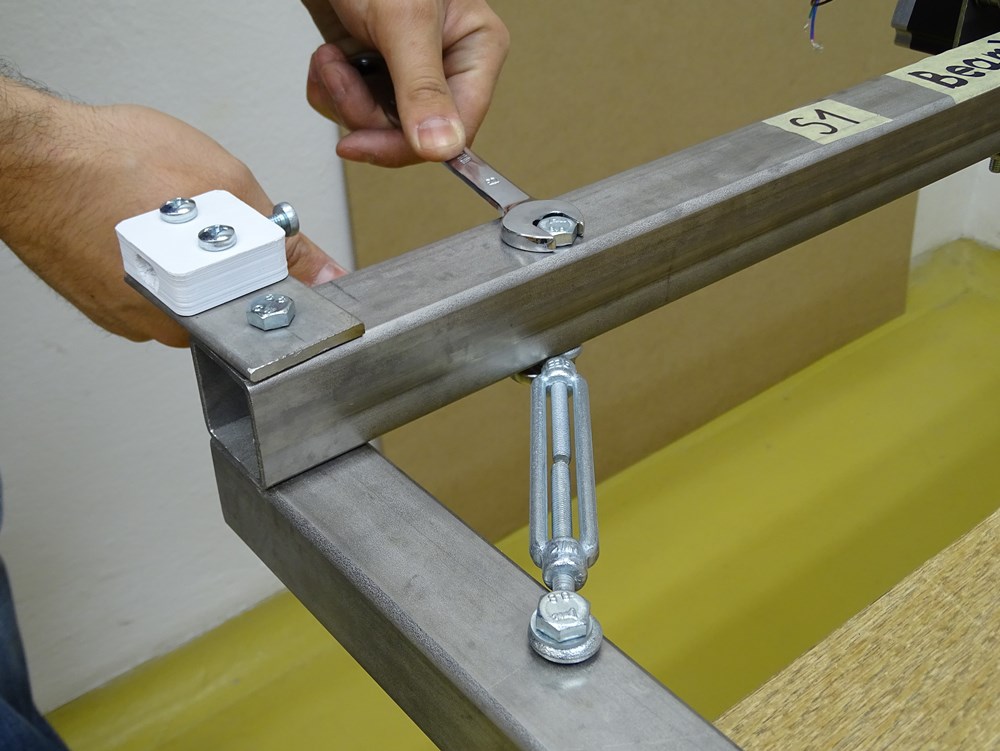
With DIN 933 M8x60 bolts, DIN 934 M8 hex nuts and DIN 125 8.4 washers mount both Turnbuckles in the corners. Use designated holes A3 and A4 on Beam X2 and A3 on Beams Y.
Parts needed
- 4 x DIN 933 M8 x 60 bolt
- 4 x DIN 934 M8 hex nut
- 6 x DIN 125 8.4 washer
- 2 x M6 2 x 70mm turnbuckle
Step 6
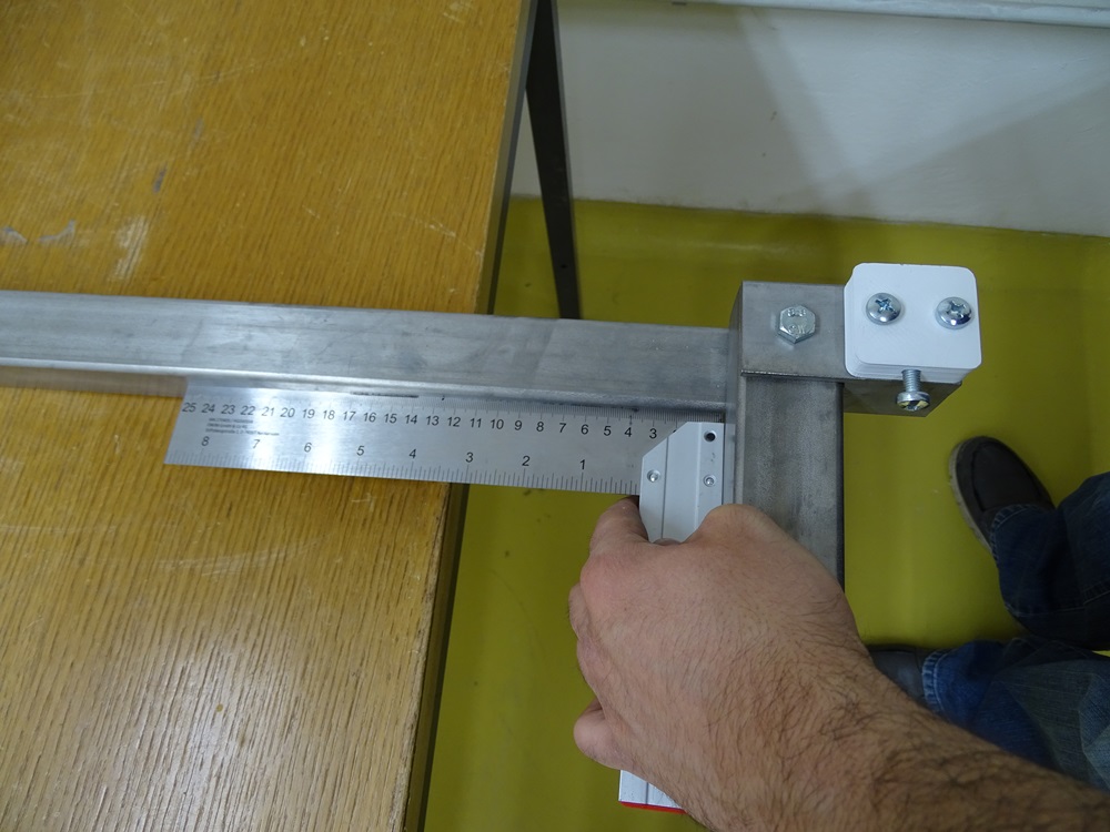
By turning Turnbuckles we can change angles between beams.
Use a machinist's square to make sure that beams are perpendicular to one another.
Step 7
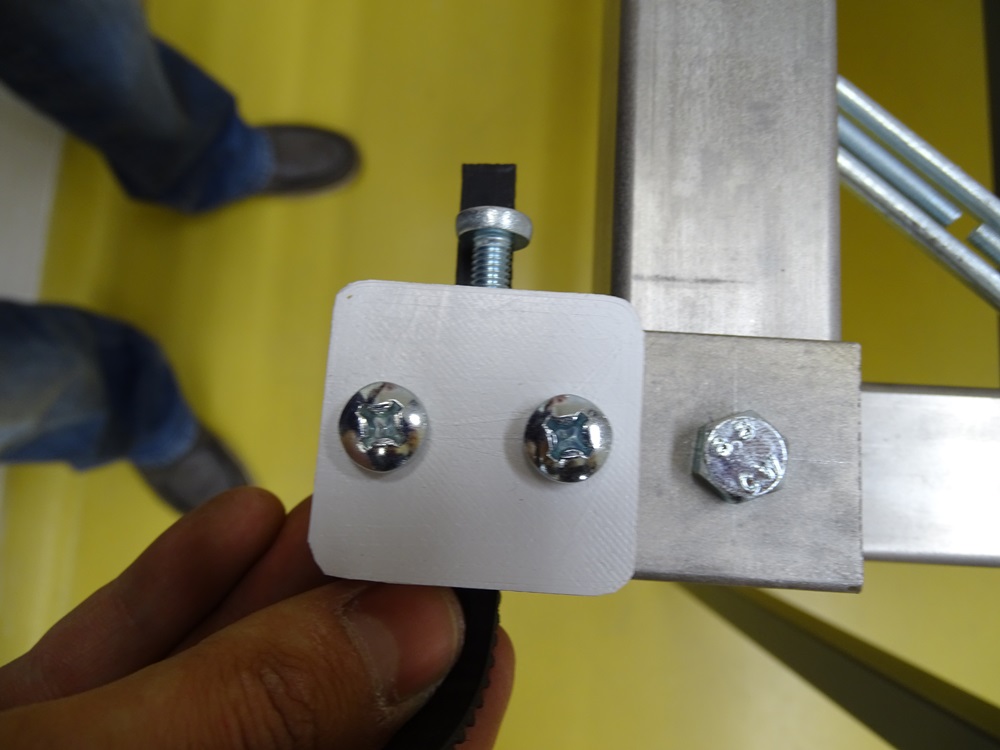
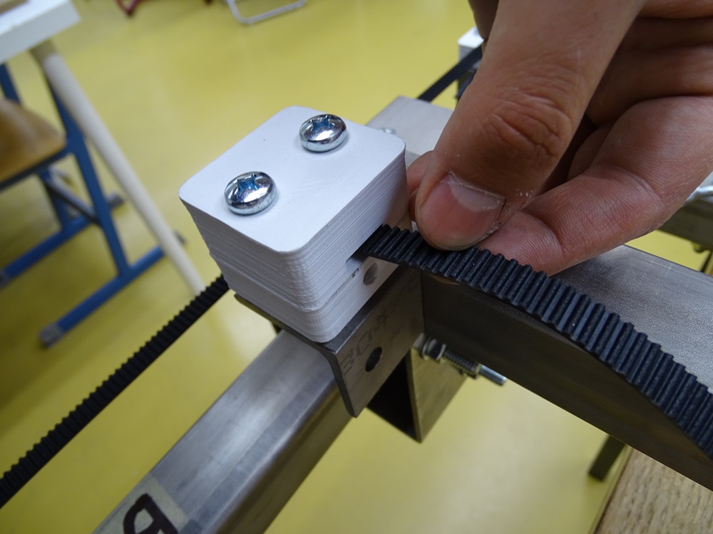
Take timing belt and put it under the tightener as shown in the picture. Secure them by firmly screwing M6 bolts with M6 hex nuts. Repeat this for both Y axes.
Parts needed:
- 2 x 1400 mm HTD3M-10 mm timing belt
Step 8
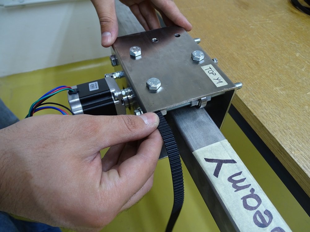
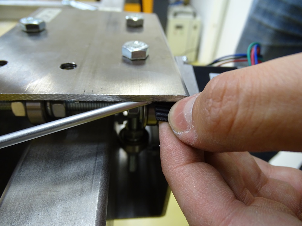
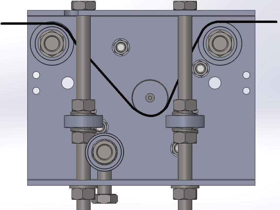
Feed timing belt into the trolleys, so that timing belt sits in the timing pulley.
Try using a narrow screwdriver to position the timing belt correctly.
Step 9
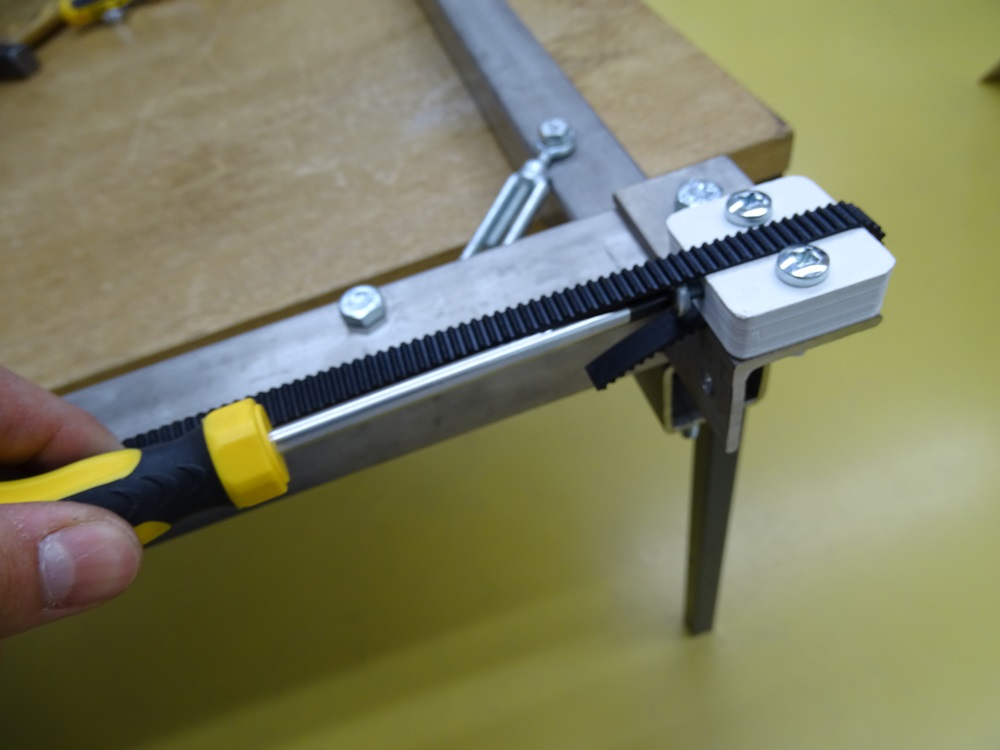
Tighten timing belts with M6 bolt on tighteners.
Step 10
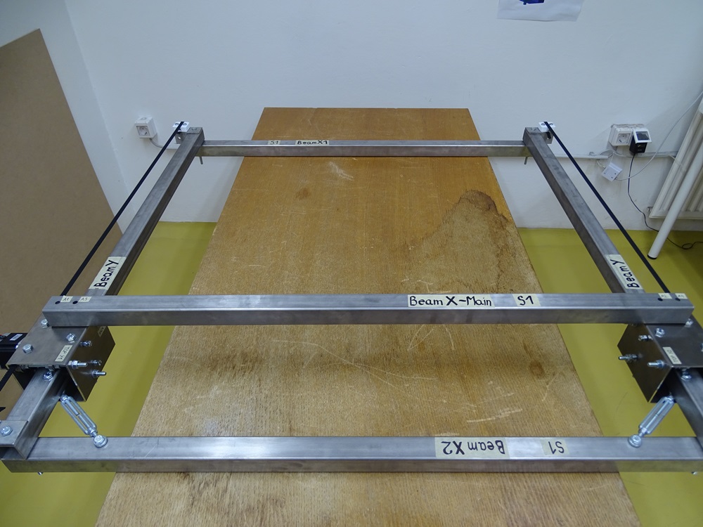
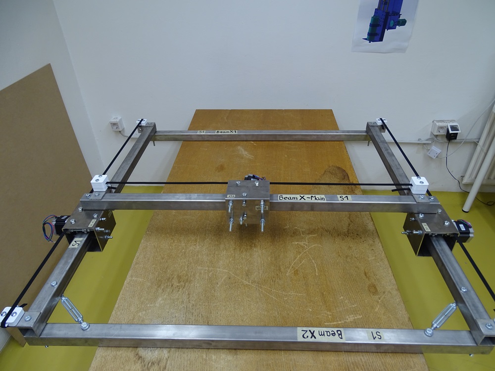
Mount Beam X – Main to the Y Trolleys as shown on the picture.
Parts needed:
- 1 x Beam X – Main
Step 11
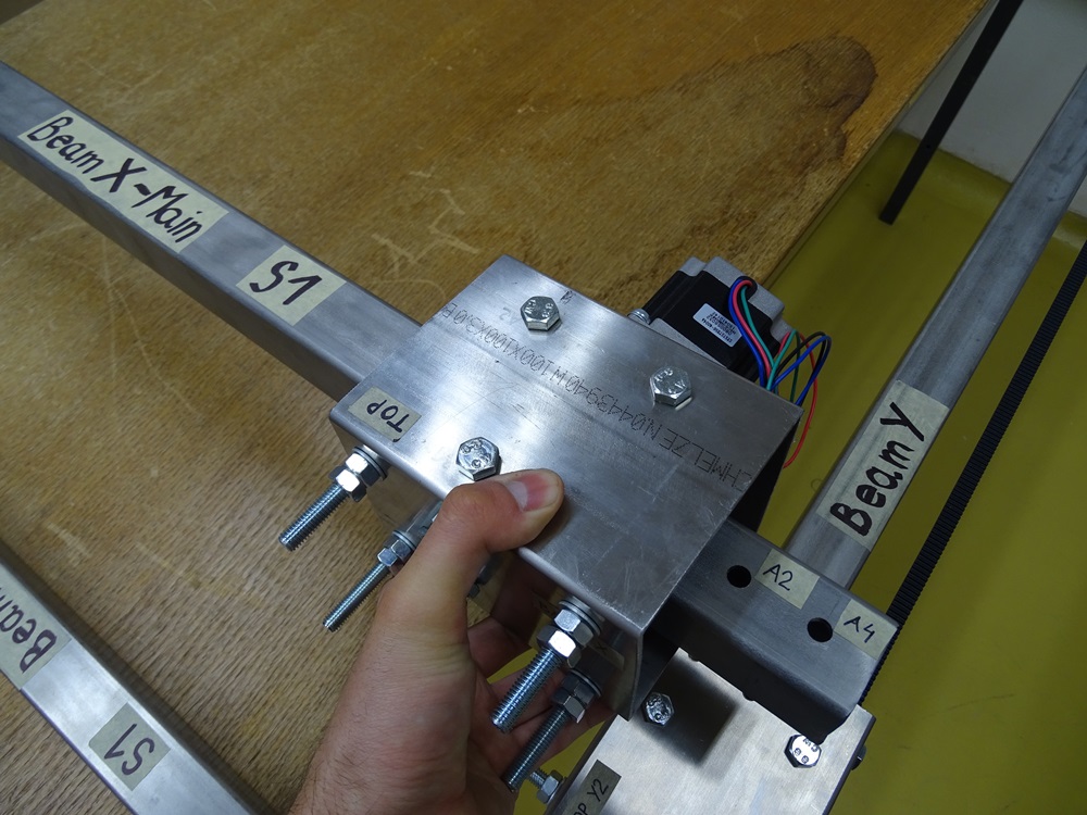
Take the Trolley X and slide it on the Beam X – Main in a manner that motor will face Beam X1.
Parts needed:
- 1 x Trolley X
Step 12
Fix the Beam X – Main on the Y Trolleys with screwing two DIN 933 M8 x 50 bolts through holes A1 and A2 on the Beam X – Main.
Parts needed:
- 2 x DIN 933 M8 x 50 bolt
Step 13
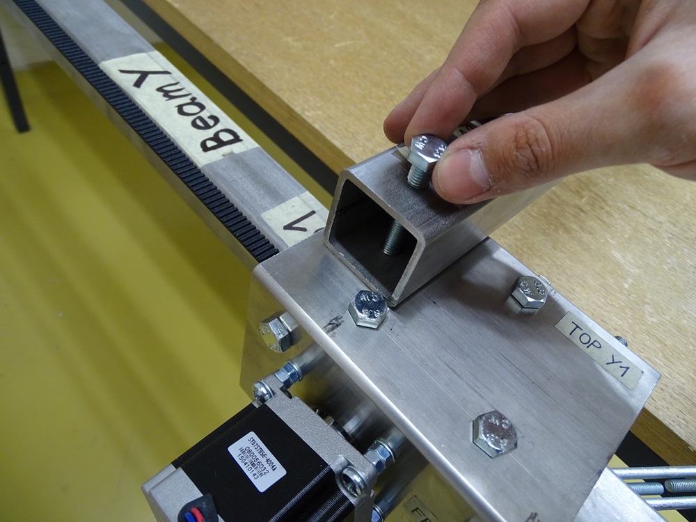
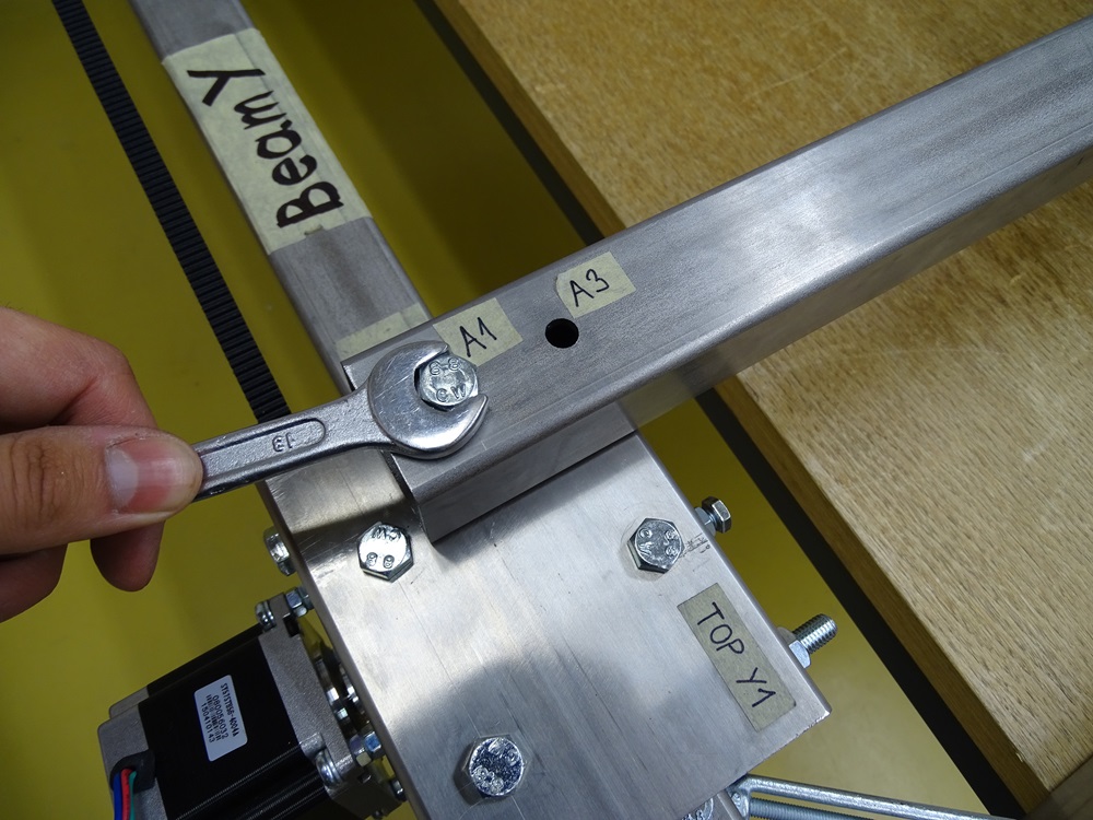
For the holes A3 and A4 use two DIN 933 M8x55 bolts. Before screwing, put on Tighteners with Spacers as shown in the picture.
Parts needed
- 2 x DIN 933 M8x55 bolt
- 1 x Tightener Assembly - Left
- 1 x Tightener Assembly - Right
- 2 x Tightener - Spacer
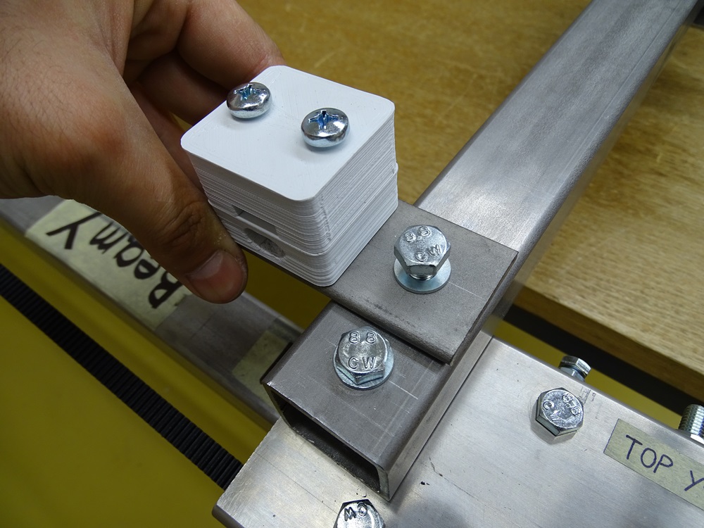
Step 14
For setting the timing belt for X axis put the timing belt through the opening in Tightener Spacer and then repeat the steps 5, 6 and 7.
Part needed
- 1 x 1400 mm HTD3M-10 mm timing belt
Step 15
Mount Z Axis Assembly on four protruding bolts on the Trolley X as shown in the picture.
Parts needed:
- 1 x Z Axis Assembly
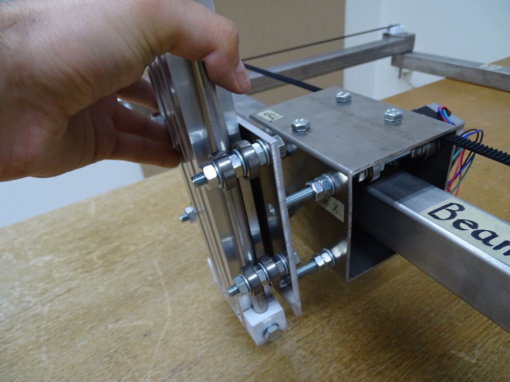
Step 16
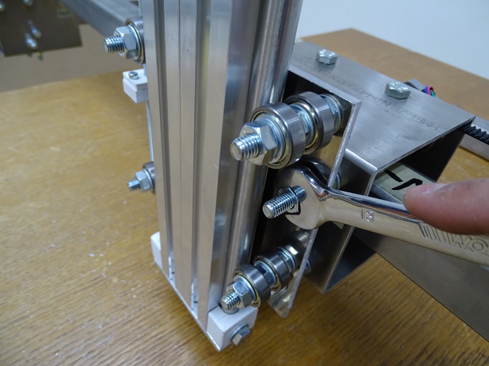
Fasten the Z Axis Assembly with four DIN 934 M8 hex nuts and four DIN 125 8.4 washers.
Parts needed:
- 4 x DIN 934 M8 hex nut
- 4 x DIN 125 8.4 washer
Step 17
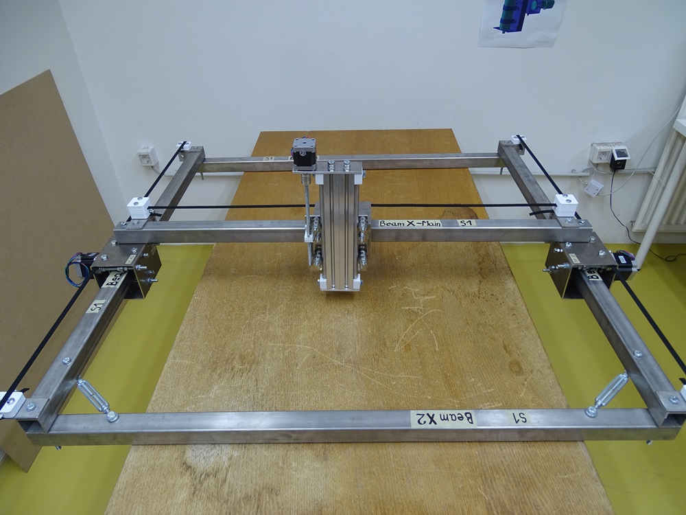
For installing the cable chain we can use simple 40 x 40 L profile 1100 mm long. For the drilling of the mounting holes in the L profile it is recommended to measure the distance between holes on opposite Tighteners on X axis. Simply drill 6 mm holes in the right positions and then fix the profile with the same M6 cross bolts that are used for fixing the Tighteners.
Parts needed:
- 1 x 40 x 40 x 1100 L profile
Step 18
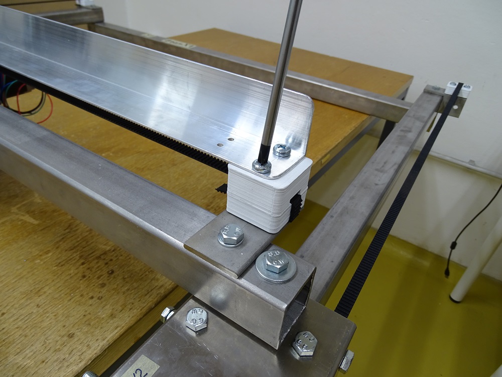
Fix one end of the cable chain onto L profile with two M4 bolts and hex nuts. Before that, drill two 4 mm holes at suitable position.
Parts needed
- 1 x Cable chain L: 1400 mm I: 25 x 15 mm R: 50mm
- 2 x DIN 965 M4 x 12 bolt
- 2 x DIN 934 M4 hex nut
Step 19
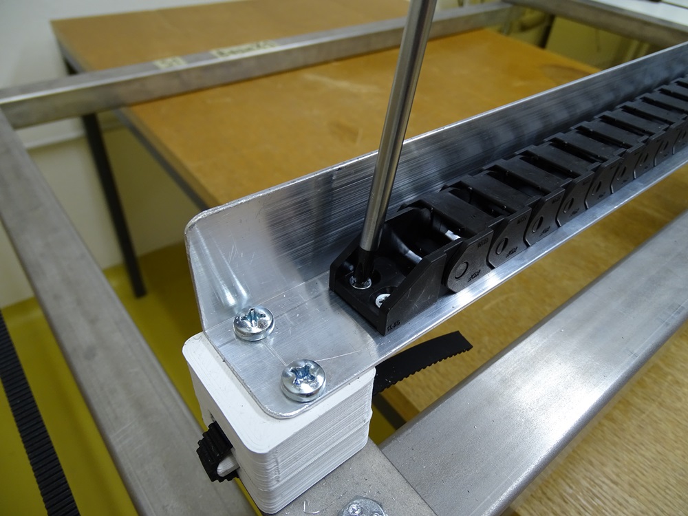
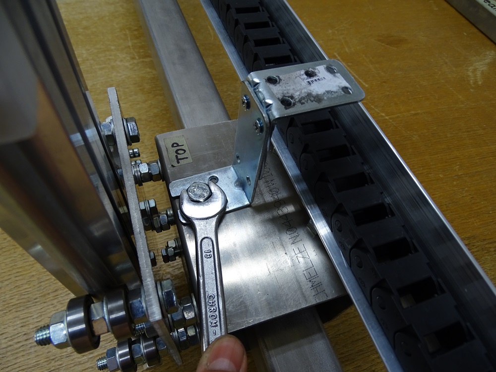
For fixing the other end of the cable chain on Trolley X use two L brackets and fix them together as shown in the picture. Fasten L brackets on the Trolley X as shown in the picture.
Parts needed:
- 2 x 80 x 80 x 30 L bracket
Step 20
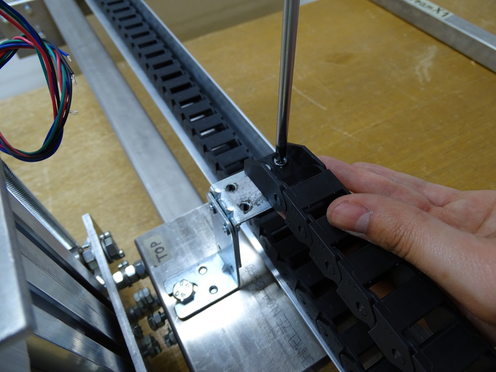
Fasten the cable chain on the L bracket with two M4 bolts and hex nuts.
Parts needed:
- 2 x DIN 965 M4 x 12 bolt
- 2 x DIN 934 M4 hex nut
Step 21
Success!
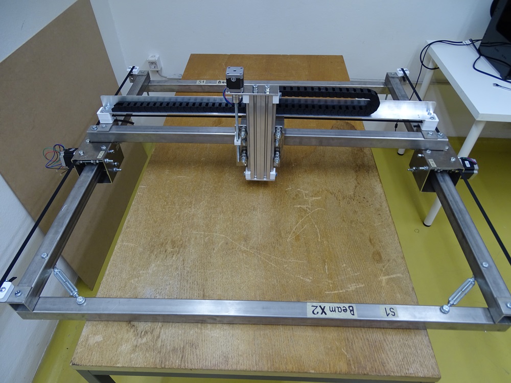
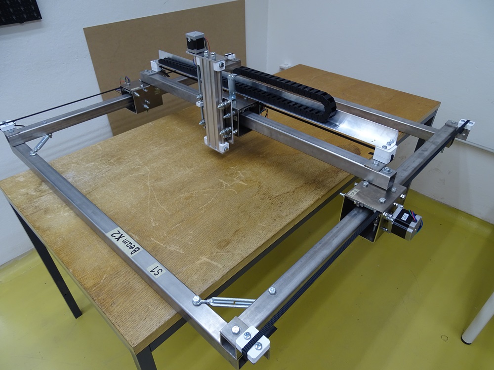
You've just built your own GoodEnoughCNC Hybrid. Now, let's start making!
Updated less than a minute ago
