Trolley - parts preparation
Step 1
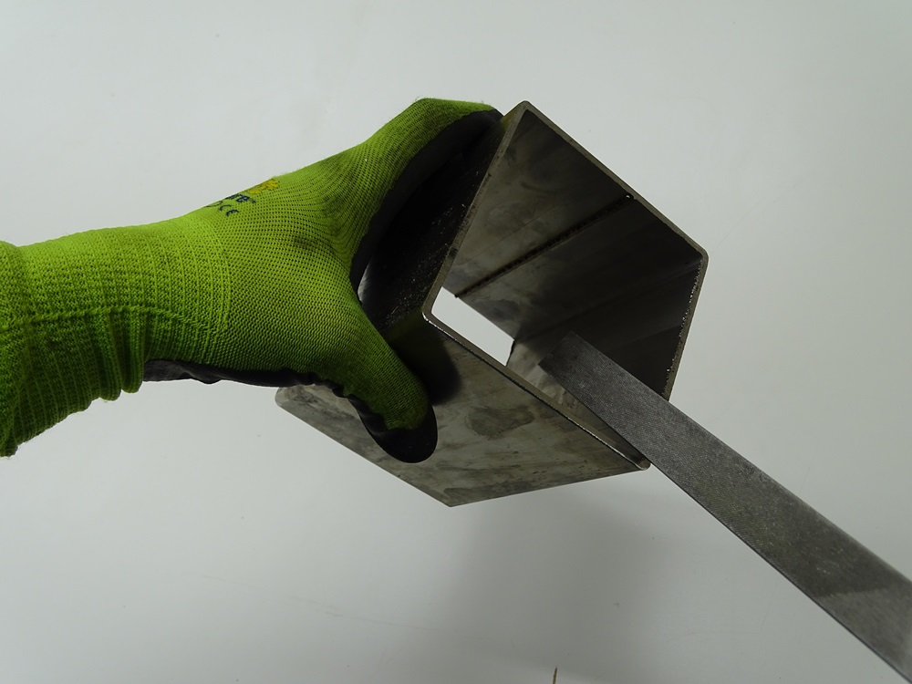
Take 100 x 100 mm with 3 millimeters thick wall square profile. Use saw to cut it 130 mm long. Be sure that the rectangular cut is achieved. Smooth the rough edges with the file.
Parts:
3 x 100 x 100 x 130 mm square profiles
Step 2
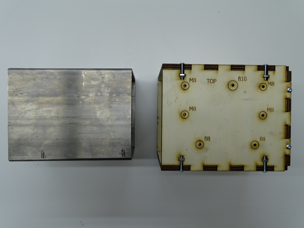
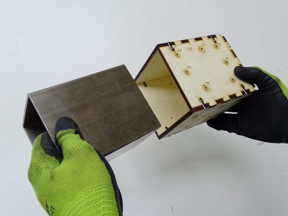
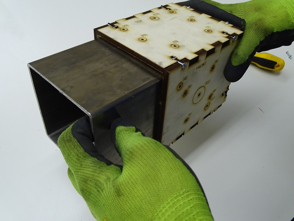
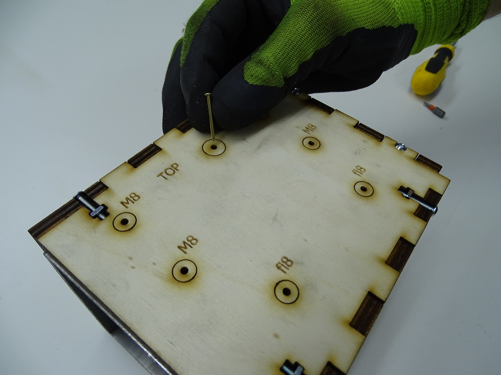
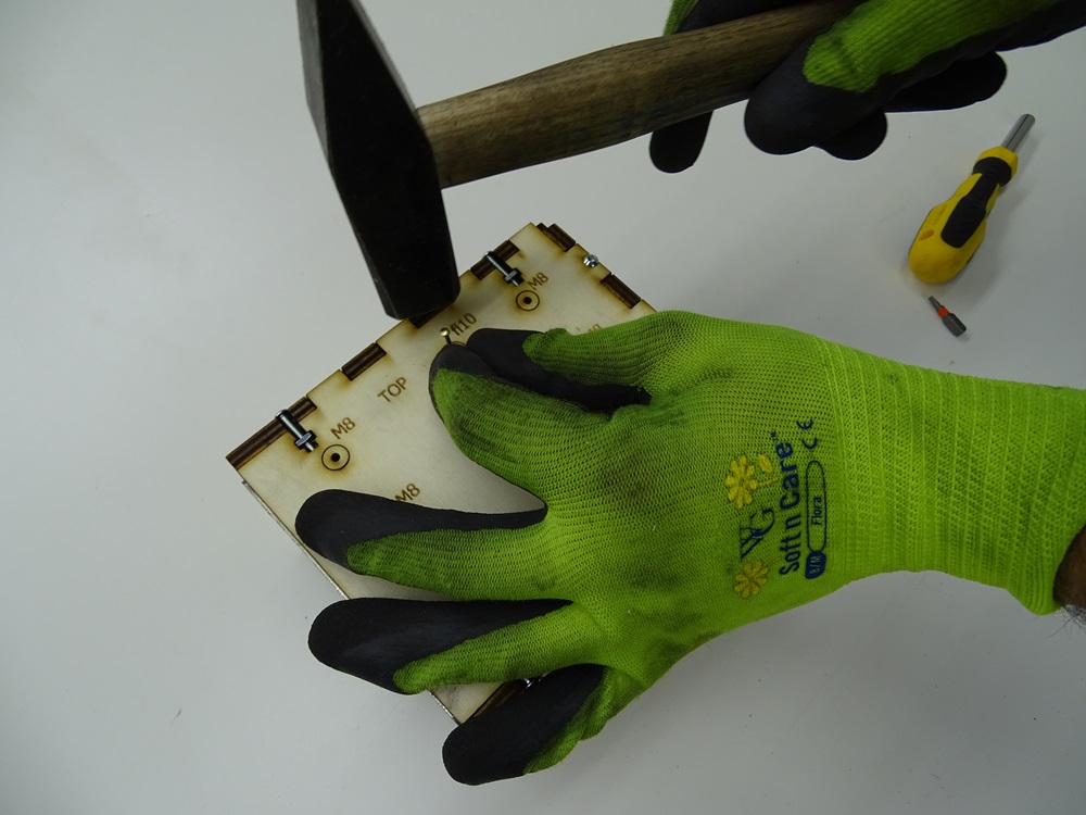
For marking the positions of the holes use laser cutted wooden box (mock up). Place 100 x 100 x 130 mm square profile into the box. Put a nail into the small holes on the box and punch it to make a mark on the profile.
For the right positioning of the holes you can alternatively use the hole table and the associated technical drawing, found on Github.
Step 3
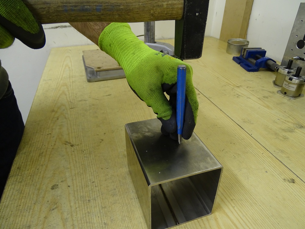
Use the center punch and the hammer to deepen the marks for the holes, which will serve as a guide for drilling.
Jump back to the Guide for Drilling Holes
If you need help with drilling holes refer to the Guide for Drilling Holes in the second section of this Step-by-step assembly instructions.
Step 4
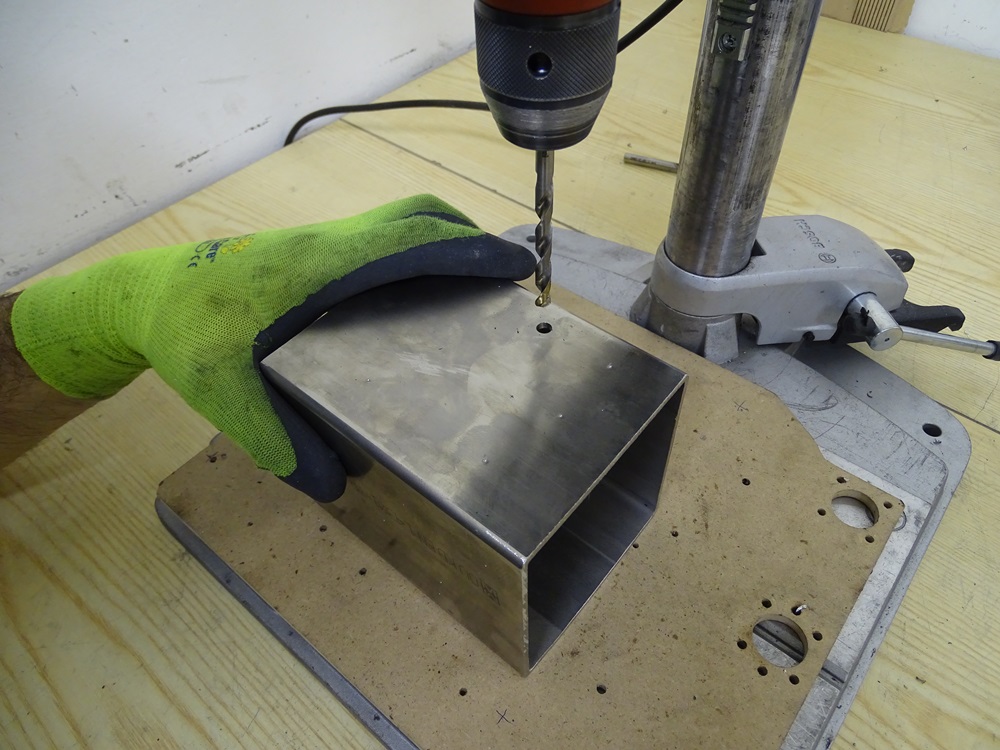
For the type and the size of the holes use a mock up box where the hole sizes are specified. Related surfaces are also marked on the mock up box.
Alternatively you can use hole table on associated technical drawing for hole sizes, found on Github.
Step 5
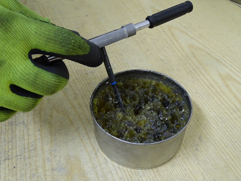
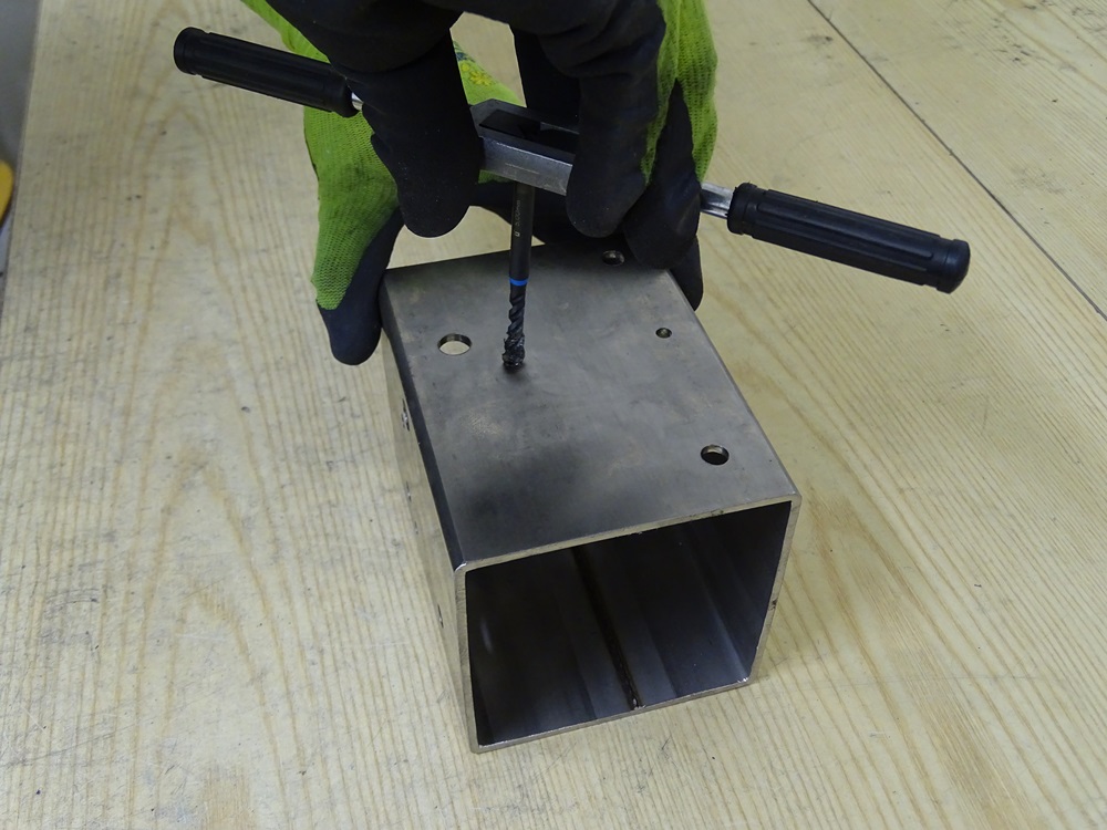
To make threaded holes, firstly drill the hole aproximately 15% smaller than the nominal value. Then use a hand tap to cut in a thread. When rotating a tap make sure that it is perpendicular to the surface.
We recommend you use machine grease to reduse friction, in order not to break the tap.
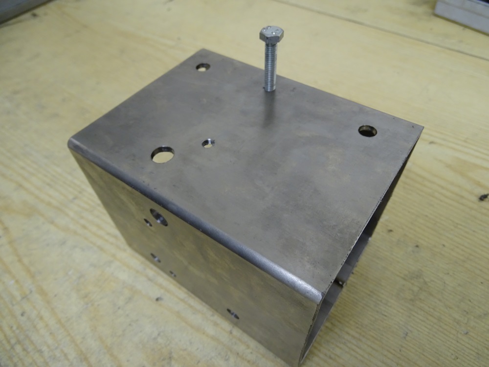
Verify the threaded hole with associated bolt.
Use additional hex nut instead
Instead of making threaded holes, we can instead use additional hex nut, which is added to the inner side of the Beam Short.
Step 6
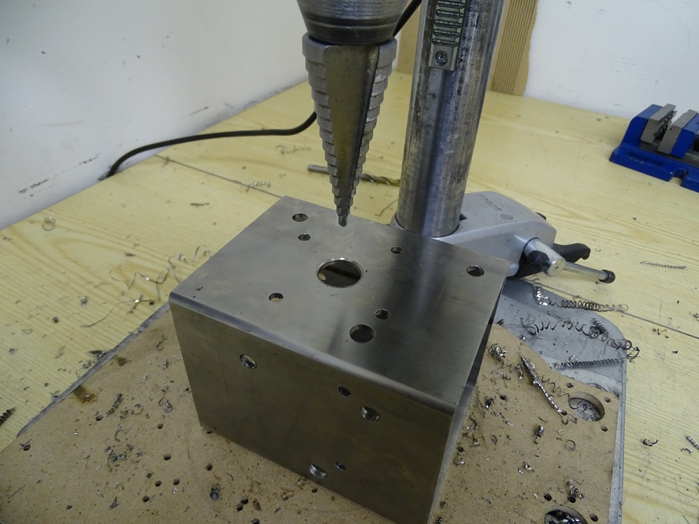
To drill a large hole on the front surface use a step drill.
Step 7
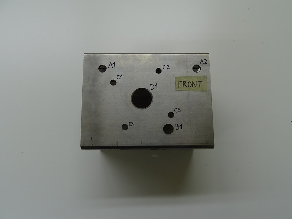
Position of the holes on the front surface. Front surface is the same for all three trolleys.
Step 8
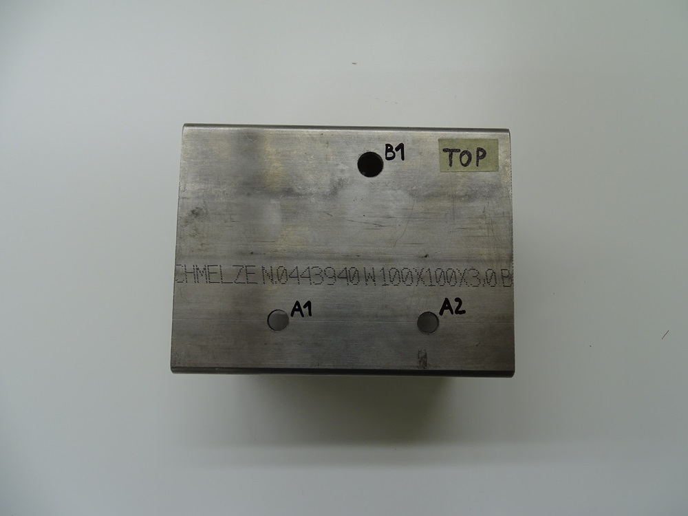
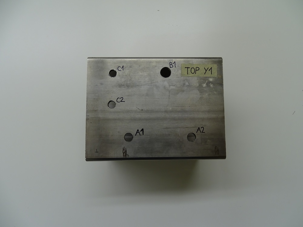
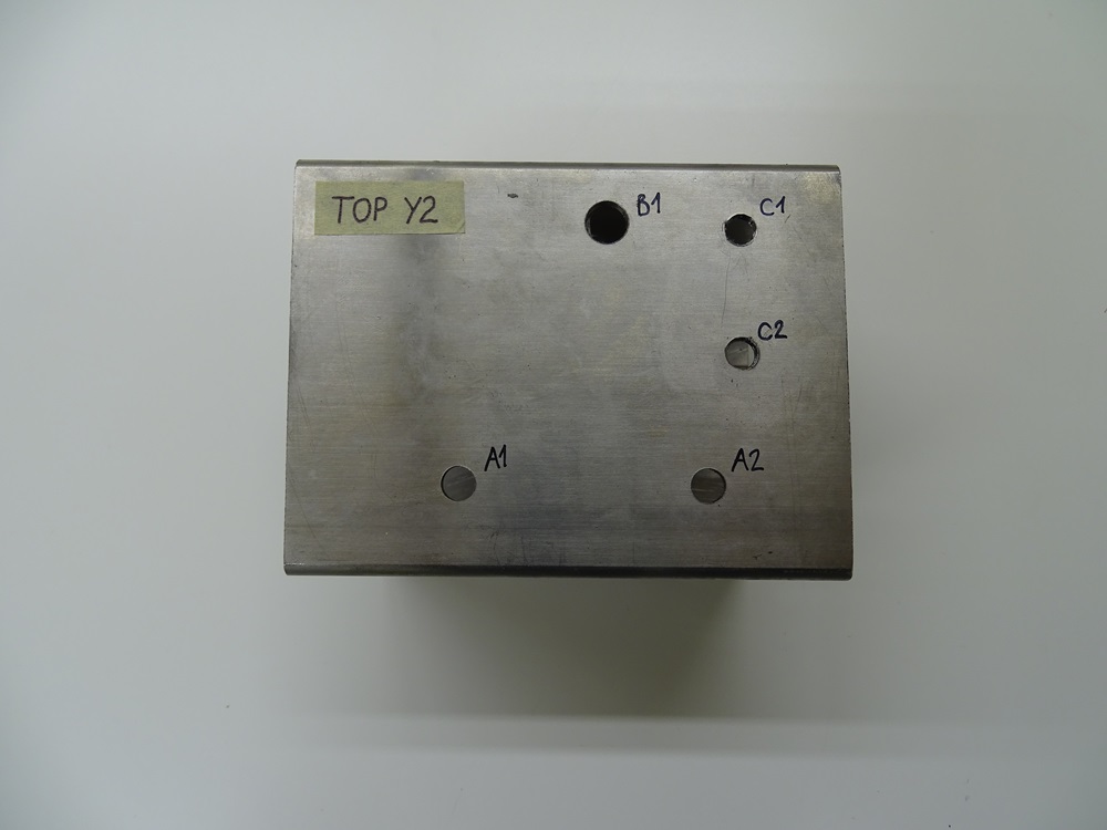
Position of the holes on the top surface. Top surface on the Trolley Y1 and Y2 has two additional M8 threaded holes compared to Beam X – Main.
Step 9
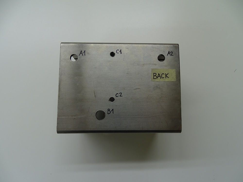
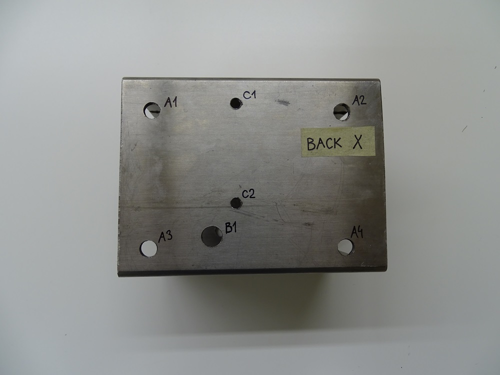
Position of the holes on the back surface. Back surface on the trolley X has two additional 8 mm holes for Z-Axis attachment.
Step 10
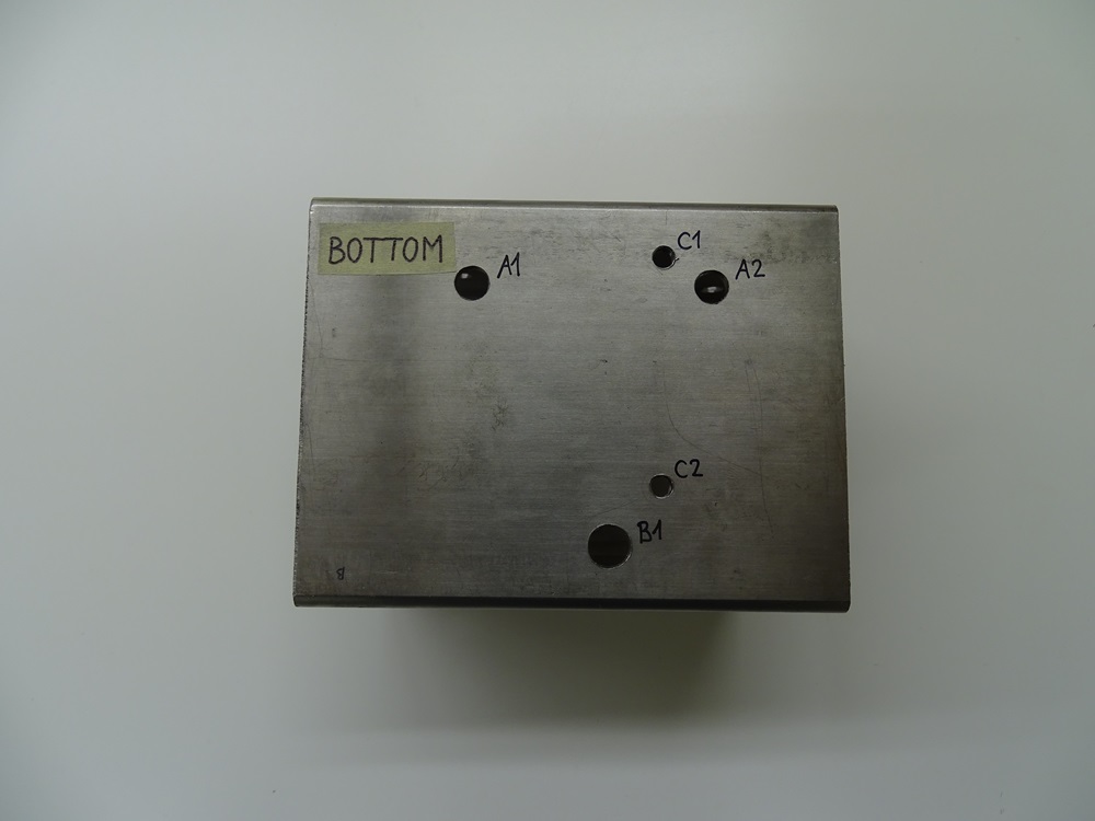
Position of the holes on the bottom surface. Bottom surface is the same for all three trolleys.
Updated less than a minute ago
